Tis the season again. Pick a (somewhat) “warm” day and get all of the Christmas decorations up. To my pleased surprise I found all of the pieces of the Mega Tree, put them together, and everything worked! How did that happen???
Night time rolled around and everything looked great. Then She Who Must Be Obeyed asked the question: “Can we add some Christmas lights to the deck railing?”
Why, yes! Yes we can!
I’ve been thinking about adding lights to the deck railing ever since we installed it. This provided the impetus to actually do something.
My vision was to add accent lighting to the bottom of the railing. You want to control the brightness, so dimming is a requirement. There isn’t much difference between white LEDs and full color LEDs, so might as well go with color changing LEDs.
Or, even better, based on my experience with the Mega Tree, go straight to computer controlled pixels. This let’s you do full Christmas effects! Clearly the only way to go.
This time use the full size LED strips which are much easier to work with than the ultra narrow strips from the Wizard Staff. The full size strips are available in outdoor versions which have a heavy silicone sheathe that protects them from the weather and from damage. And they have an adhesive backing, so just peel ‘n stick on the bottom of the railing.
Right. You know better than that…
I don’t trust adhesive to stand up over the long term for applications like this. They also make a U-shaped aluminum channel for mounting LED strips. These channels have a snap in plastic cover that locks into place over the LEDs making sure they don’t go anywhere. Even if the adhesive fails completely everything is still secure.
And the channels are white, so they will blend invisibly into the white railing.
These channels are commonly held in place with double sided tape. Or…. You can run screws through the bottom of the channel. But the railings are (heavy) steel – you can’t run screws into that.
But you can drill and tap holes for machine screws. And I have drill bits. And taps. And a box of 8-32 stainless steel machine screws.
Order the LED strips, aluminum channels, and the electrical cable to wire everything up.
Drill and tap the holes in the bottom of the railing. Since I am experienced and careful I was able to accomplish this with only one broken tap. Screw the channel into place. Hey, it does disappear!
Now to install the LED strips. Thes strips come in 16.5 foot (5 meter) lengths. The long side of the deck is 22 feet. And I need a right angle connection.
Unlike my experiences with the ultra narrow LED strips, these full size strips are easy to work with. Cut to length, solder wires to the pads, and cover the connections with hot glue to protect and insulate. Check the full length on the bench and everything works.
Take the 30 foot long LED strip to the deck, peel off the backing, and stick it inside the channel. Come back and pop in the plastic covers and Viola! Done!
Hook up the WLED controller and test it. Still working! And there was much rejoicing!
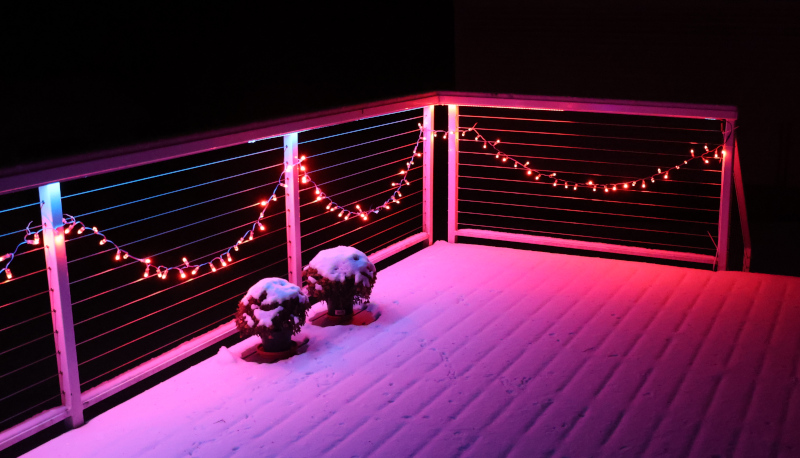
Wait for nightfall, fire it up, choose some different WLED patterns, and admire my handiwork.
It was boring. It worked perfectly, but had no impact. You couldn’t see the LEDs – they were inside the channel, behind a diffuser, and below waist level. The light was shining down on the deck providing the accent light I had originally envisioned. It was nice, but it just wasn’t Christmas.
Crud.
To be continued…