
In the Electrical 3: Bulkheading we replaced the factory connector with a new more modern design. Like the bulkhead connector, the fusebox under the dash is is old and crufty.
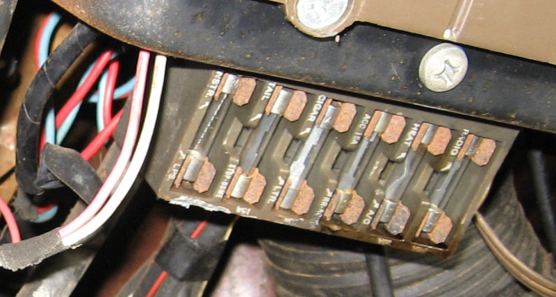
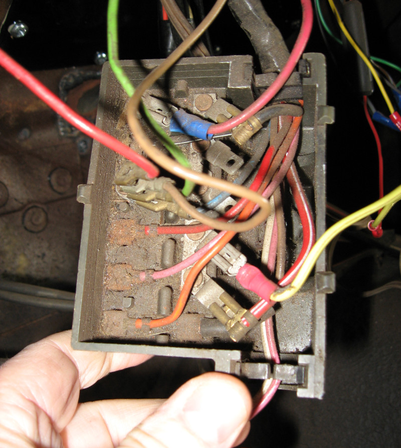
In addition to rust and using old style glass fuses, this old fusebox only supports 6 circuits. This makes it difficult to add new electrical devices. In addition, some circuits are outside this fusebox. For example, the power windows and power seat are on a separate subsystem.
I’m replacing this with a Bussmann Series 15305-1 fuseblock. This includes dual power busses, space for 20 automotive fuses, and is designed for Metri-Pack 280 series connectors. An interesting aspect of the Metri-Pack 280 is that the connectors are the same size as automotive mini fuses. This means that automotive mini fuses can be plugged directly into Metri-Pack 280 female connectors. Using the Bussmann fuse block all you have to do is install a Metri-Pack connector onto the end of a wire and insert the wire into the fuse block and then you can plug in a fuse. Each power buss in the 15305 is capable of handling 100 amps and each fuse can be up to 30 amps.
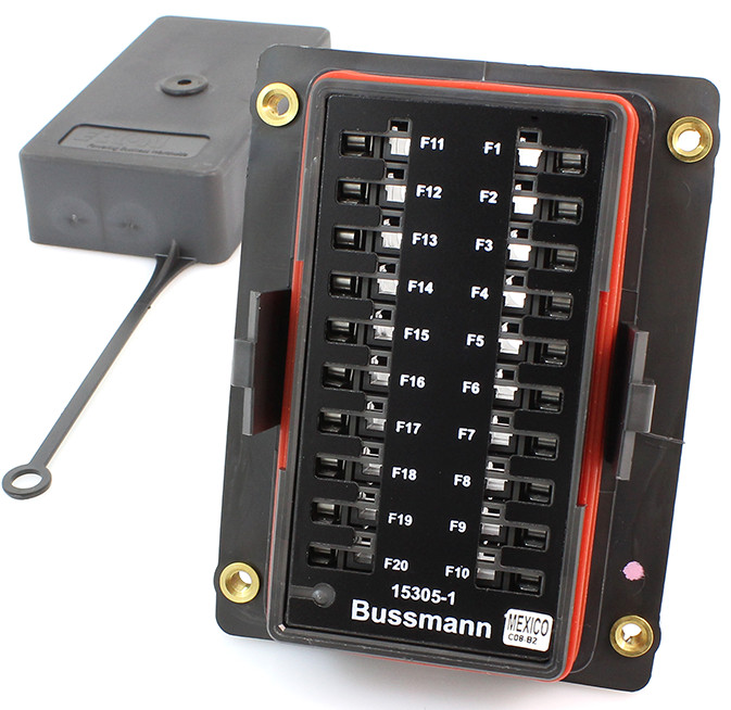
The power busses are connected to the new bulkhead connector described in a previous post. It is currently using the factory wiring configuration; ultimately each bus will be supplied by 3 wires and capable of delivering 60 amps of power.
The process of wiring the new fuse block is the same as wiring the bulkhead connector: Start by building a diagram of circuits.
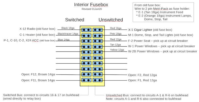
Using this plan I then went through the process of cutting the wires, adding labels and new connectors, and then plugging into the new fuseblock.
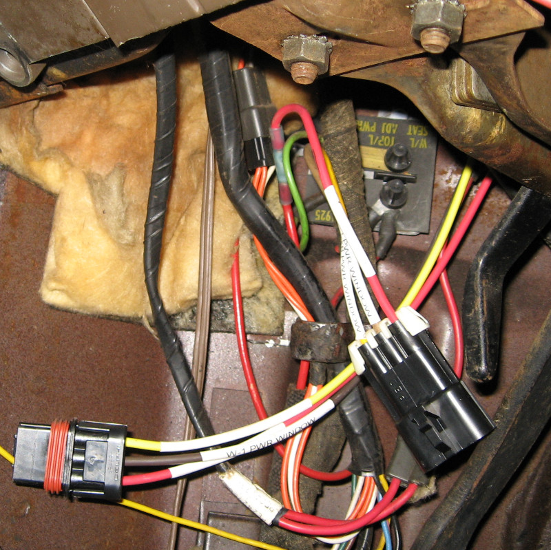
The power seat and power window wires were removed from the existing circuit breaker, terminated into a WeatherPack 3 circuit male connector, and three new 12ga lines were run from the new fuseblock (F-2, W-1, and W2B in the diagram above) to a WeatherPack 3 circuit female connector (shown here disconnected).
There are now plenty of extra circuits available. After connecting all of the factory wiring I added four additional circuits for future use. Each of these is 1′ long and has a Metri-Pack 280 series female connector installed. I can wire in new devices by putting a Metri-Pack connector on their power line, plugging it into one of the open wires, and adding the appropriate fuse. This avoids having to remove the fuseblock to get to the back side to add a new circuit.
If needed I can add an additional seven switched devices and five unswitched devices – this should provide plenty of expansion capability!
There was one special case: the instrument cluster lighting is on a dimmer circuit which changes voltage – this circuit can’t be connected directly to a power bus. I connected each side of the instrument cluster lighting to a Metri-Pack 280 series female connector and plugged in the specified 1 amp fuse. It is really convenient building fused circuits using the Metri-Pack system.
Next: something a bit different with Workshoppery.
Next electrical: Electrical 5: Boxing
If you wouldn’t mind clarifying. How can you add 7 switched and 5 unswitched when your fuse box diagram is showing 5 and 3 open spaces?
The power for the instrument lighting comes from where such that you have put a fuse inline? Are you saying you put the fuse inline after the dimmer which is part of the light switch?
Daniel, excellent questions!
For the first question, on the switched side there are three circuits connected. When wiring up the fuse box I connected two additional slots with foot long wires ending in a female connector; these are the ones labeled Open. I can add two additional devices simply by connecting to these wires. The remaining five slots on the switched side are empty because I didn’t want too many loose wires under the dash. If I need more circuits I can drop the fusebox and add additional circuits directly into the fuse box. It is a bit of work to drop the fuse box, but not too bad.
This leaves us with 10 switched circuits: three in use, two wired and ready to use, and five empty, thus giving us seven available circuits. The unswitched side is five in use, two wired and ready to use, and three empty, making five available circuits.
The instrument panel lighting is very interesting. 1961 through 1963 Imperials used electroluminescent lighting for the dash – the dash panel actually glows! The power for this is special: 200 volts at 200 hz AC power coming from a high voltage power module. This power module takes 12V input from the rest of the dash wiring and provides 200V output.
The power for this comes from the headlight switch, specifically the dimmer in the headlight switch, and goes to the dash lighting circuits – just as you suggested. Unlike the rest of the fuse block, which use switched and unswitched power busses, the fuse for the dash lights is an in-line fuse. Since you can’t use the Bussmann fuse box for this, I added an inline fuse by using a two conductor female MetriPack connector as a fuse holder. Unfortunately it isn’t visible in the pictures.