
After Retiring the Imperial it was time to get back to electrical work. Electrical 4: Modernizing the Fusebox covered updating the old fusebox under the dash. I’m now at the point where I can start working on adding a high power fuse/relay box in the engine bay that will both completely bypass existing wiring for high current devices as well as provide more power for the upgraded interior fusebox.
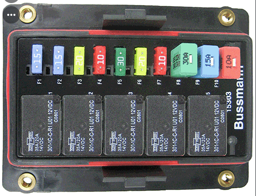
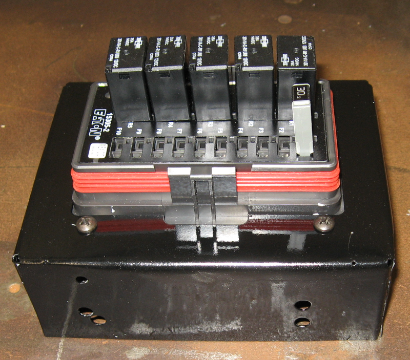
The fuse/relay box used was a Bussmann 15303 which provides five relays and ten circuits protected by fuse or circuit breaker. It is a weatherproof box which uses MetriPack 280 terminals and includes two 100amp internal buss bars.
Since the new fuse/relay box is roughly the size of the already removed AutoPilot, the plan was to install it where the AutoPilot used to be. Unfortunately you can’t just “put the fuse/relay box under the hood” – you need something to hold in in place: a bracket!
I had done a simple bracket for the interior fusebox, which I wasn’t completely happy with. The Bussmann box requires a fairly complex cut-out which I had done by hand. Crudely. You can’t see it under the dash, but the under hood location will be more visible. In addition, the under dash bracket was a simple bent flat sheet, while the new bracket really needed to be a box. Not only that, but a box that serves several purposes beyond simply holding the Bussman 15303.
As part of my tremendously successful ongoing program of making simple tasks complex, I decided to design the bracket as a 3D Solid Model using the Autodesk Fusion 360 CAD program, unfold the 3D part into a 2D flat pattern using the Fusion 360 Flat Pattern module, and have it laser cut from steel by Send Cut Send. This is in contrast to the Cardboard Aided Design and hand grinder with cutting disk approach which is commonly used to design brackets.
Many years ago (I decline to say how many…) I was a Computer Aided Design – CAD – expert. I designed jet fighters (OK, I was a junior engineer on an 8,000 person design team) using a state of the art CAD system to design complex parts, mostly in sheet metal and composites. It has been years since I did any CAD work and I wanted to get back into it using the latest technology.
Fusion 360 is an incredibly powerful Solid Model based design and drafting system which is currently available to hobbyist under a one year zero dollar license – in other words “free”. To summarize my view of Fusion 360: WOW! Where was this technology when I was designing things for a living? A couple of tiny nits: Fusion 360, like all powerful software, has a learning curve. Solid modeling is very different from the wire frame based systems I learned on. And I’ve forgotten most of what I used to know…
After a few weeks of fighting Fusion 360 I had an initial design to be bolted to the inner fender:
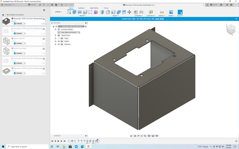
This design didn’t work – too big and there was no place to attach it to the fender. So, back to the “drawing board” and come up with a modified version:
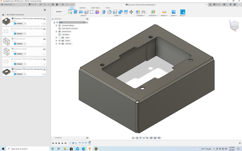
It was incredibly simple (OK, simple the 5th time I tried to do it) to do this design in Fusion 360: Design the top surface with the cutout and then select an edge and specify how long this flange was. In the case of tabs on a flange, just select an edge of the flange and specify how long the tab was. These flanges could be edited, so I added 3/8″ holes to allow plug welding the flanges to the tabs after folding the metal part.
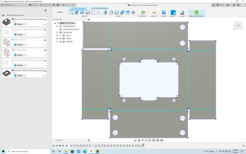
After completing the 3D design the 2D flat pattern was produced simply by picking the 3D model and executing a single Unfold command:
With the design done it was time to send it out for fabrication. Send Cut Send is basically a “sheet metal print shop” which uses a laser cutter to cut precision parts out of steel, stainless steel, aluminum, copper, brass, titanium plastic, carbon fiber composite, wood, and other materials based on customer electronic design files. Sheet metal is a bit of a misnomer – they can cut metal up to 1/2″ thick! They can handle anything that can be cut out of flat stock, and are set up to produce from one to several thousand copies of a single part.
Send Cut Send has an interesting business model: they have a fully automated price quoting system to price per part with a $29 minimum order. They have fully automated all of their processes and they buy materials in large enough quantities that you can often get complete finished parts for less than what it would cost you to buy the raw materials!
I uploaded the flat pattern and started a new order specifying 22 gauge (0.030″ thick) steel. Hmm, the part is going to cost $9.37. I can order either one part or three parts for the same $29 minimum charge. Decisions, decisions… OK, three parts it is!
A few days later a package showed up with the parts ready to bend up.
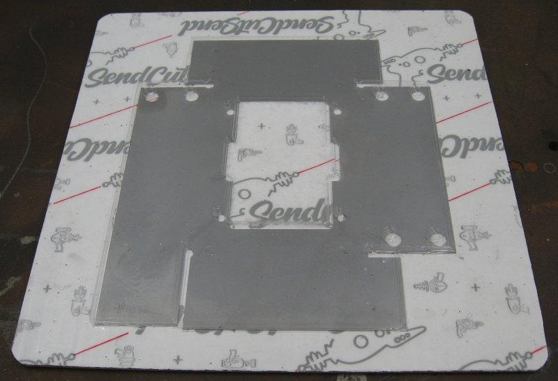
With three parts I could afford to screw up two, so I grabbed the top part and started building up a prototype. First, bend the flat parts into the final box:
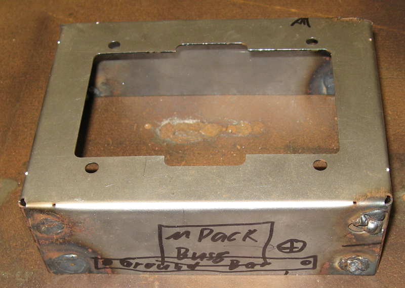
“Plug weld” means welding through a hole to the metal behind it, and is a powerful tool for working with sheet metal. I forgot to turn on the gas in the MIG welder for the welds on the right – they are complete garbage. The welds on the left, with gas, are much closer to what they should be.
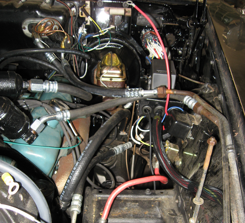
There were many details to work out on how and exactly where to mount the box, wire routing, and grounding. Mistakes were made — I mean “several options were explored in order to determine the best final approach”.
That description is way to simple. The reality was THE BLOODY BOX DIDN’T FIT NO MATTER WHERE I TRIED TO PUT IT! No matter what I tried, something was in the way! <Calm down, calm down…> The engine bay of the Imperial is surprisingly small. The area where I needed to put the box in was cris-crossed with lines, hoses, wires, boxes, and assorted parts. Not to mention THE FREAKING HOOD HINGE WHICH LOOKS LIKE IT IS OUT OF THE WAY UNTIL YOU TRY TO CLOSE THE FREAKING HOOD.
Ahem. After trying many different approaches I finally succeeded in finding a location that would work and built additional mounting brackets to actually support the box.
After getting something I was happy with the good elements were transferred to the second part which was then folded, welded (this time with gas), finished, and painted. Here is the finished mounting box with the fuse/relay box installed:
Next: it’s not a good day when you have to be Towed.
Next electrical: Electrical 6: I Need Power!