
As described in the previous article Towed the Imperial is waiting for parts. Which means that it is a good time to get back to the electrical work last seen in Electrical 5: Boxing. With the location and mounting of the new fusebox resolved the next step is to fill up the fusebox.
The plan is to completely replace the existing under hood wiring harness with all new wires. Everything from the new bulkhead connector forward is being replaced – and upgraded. In addition to installing new wires, I’m increasing the size of the wires: 18ga is replaced with 16ga, 16ga is replaced with 14ga, 14ga is replaced with 12ga, and 12ga is replaced with 10ga. This is probably overkill, but there is very little cost difference in going one size larger on wire.
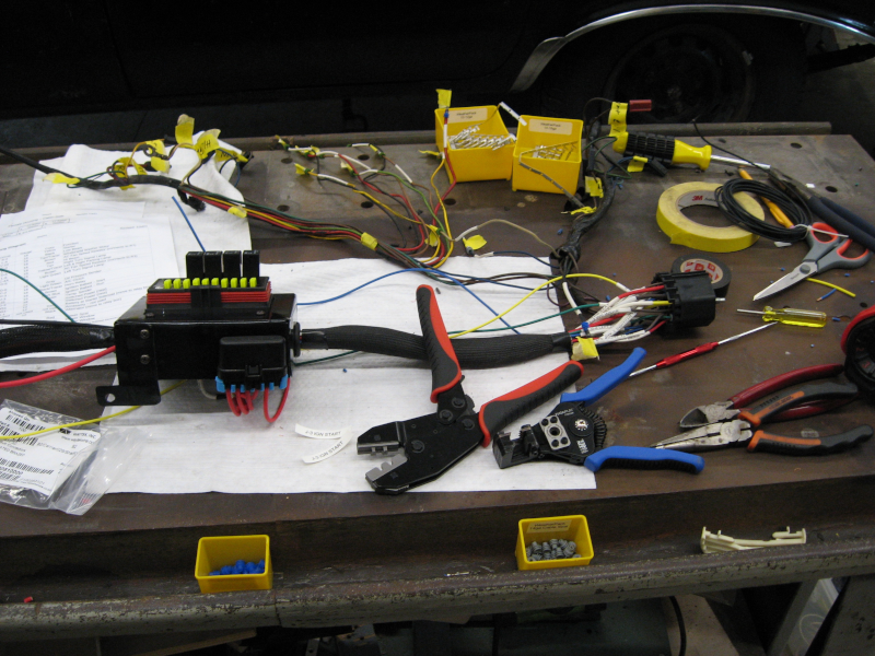
The process for building the new harness is straightforward. It is also time consuming and tedious…
To start, mount the new fusebox and measure the distance from the bulkhead connector on the firewall to the fusebox. This is the length of the new wires to the fusebox. As this will ultimately be a large stiff bundle of wires it is critical to get the length right.
Remove the new fusebox and take it over to the workbench. Dig out the carefully planned wiring diagrams that show where everything will be connected in the fusebox and how the wires are arranged in the bulkhead connector.
The new Bussman 15303 fuse/relay box has two power busses. One bus is used to provide all power – it supports 10 fuses and is rated at 80 amps which should be more that adequate. The other bus is used to ground pin 85 on the relays; this is a low power application, but simplifies wiring.
Wiring the relays requires four connections: power, load, signal, and ground. Power goes from the power busbar through a fuse to the power side of the relay and then from the load side of the relay to where it is being used. The original power for each circuit is now used merely as a signal to the relay.
The first step is to wire a 12ga jumper from a fuse to the power side of the relay (pin 87) for all five relays. Wiring it this way means that the relay is protected by the fuse. Since the relays are the most complex part of the new harness they are wired first. The Bussmann box has considerable flexibility and can be wired with or without relays.
The original headlight wiring is a joke. Power for all four high beams was run through a single 16ga wire. A long run of 16ga wire, going through the headlight switch. Even if this were capable of safely carrying the current, the voltage drop through this tiny wire greatly reduces the brightness of the headlights. According to Danial Stern Lighting a 1 volt drop reduces light output 30% – going from the rated 12.8V to 11.5V reduces a 1,000 lumen headlight to 693 lumens. Going down to 10.5V takes the headlights down to a mere 510 lumen – a loss of 1/2 of available light!
The original headlights were 35 watts. Running the 4 Hi beams would be 140 watts or 11 amps. New headlights typically draw 55 watts or higher, with 65 watt high performance bulbs readily available. The headlight system needs to be designed to handle 260 watts with minimal voltage drop. And without burning up the headlight switch – at 12.8V, 260 watts is over 20 amps! 16ga wire is rated for 10 amps, meaning that it is marginal for the original bulbs and too small for modern bulbs.
The new design uses relays with a dedicated wire directly from the relay to each headlight. The original plan was to also have a dedicated ground for each headlight, which would require five wires to each side (two headlights per side): hi beam 1, hi beam 2, low beam, ground 1 and ground 2. A four wire connector is easier to fit through the holes, so the design was modified to hi beam 1, hi beam 2, low beam, and ground. To compensate for this the ground wire is now 12ga for two headlights instead of 16ga for four headlights.
14ga wire is plenty to power the headlights, especially with the short run from the relay to the headlights. Looking through my wire supply turned up longer rolls of 12ga than 14ga. OK, overkill it is – 12ga for all the headlights!
Time to start wiring. The old wiring harness was placed on the workbench next to the new fusebox as a reference. Using the low beam headlights as an example: The low beam is identified as circuit L-4, a black wire installed in pin C of the bulkhead connector.
Since this is now just a signal wire, a piece of 16ga black wire is cut to the length previously measured from the new fuse box to the bulkhead and labeled (with shrinkwrap labels) as “L-4 LO BEAM”. Actually, this wire is cut a few inches long; we will trim all wires going into the bulkhead to the same length at a later stage. A MetriPack 280 connector is installed on one end and plugged into the fusebox on pin 86 of relay 1. The wire is routed out of the fusebox where it will later be gathered into a bundle.
Next, go to the old harness and measure from the location of the fusebox to the left side headlight connector. Cut a black 12ga wire to this length and label each end “L-4 LO BEAM 1”. Cut a white 12ga wire to the same length and label each end “HDLT GRND 1”. Might as well take care of the HI beams at the same time, so measure and cut two pieces of red 12ga wire and label them “L-3 HI BEAM 1″ and L-3 HI BEAM 2”.
Since there are four headlights on the car, measure the length to the right side headlights and cut and label the four wires.
For the Low beams there are two wires going to the relay. Using a heavy duty butt crimp connector, the two wires are stripped, wrapped together, and crimped into one side of the connector. A short 12ga jumper wire is crimped to the other side of the butt connector and the whole thing is sealed with marine grade heat shrink tubing. A MetriPack 280 connector is crimped onto the jumper wire and plugged into pin 87 on relay 1.
The Hi beams are done the same way. You can’t run four 12ga wires into a butt connector, so a small weather proof buss bar is used instead.
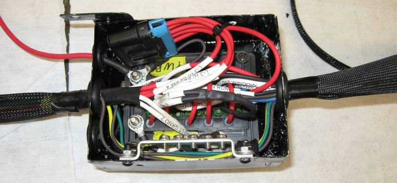
A grounding buss is mounted inside the mounting box for the fuse box. The headlight grounds and relay ground are connected, along with a 10ga wire going to the chassis ground bolt.
One challenge with upgrading power is that the Weather Pack bulkhead connector only supports 20 amps per pin. Of course this implies that two pins will support 40 amps… So, run two wires with 20 amp fuses from the new fuse box to the bulkhead. On the inside, run two wires from the bulkhead connector to the unswitched power buss on the interior fusebox. Bingo, 40 amps of power is now available from the fusebox!
Switched power is done the same way using two relays. The ignition circuit, J-2, which provides power to the ignition coil, is live whenever the car is turned on. This circuit is tapped to provide a signal to relays 3 and 4. These relays are connected to the bulkhead connector, providing 40 amps of switched power to the interior fusebox.
One of the side effects of being forced to remove the AutoPilot cruise control is that the three control wires for cruise control are no longer needed and could be removed from the bulkhead connector. This made it possible to directly connect the power seat and power windows directly to the new fuse box. I had previously added a MetriPack 280 connector to these circuits. New wires were run from this connector to the bulkhead, and new wires run from the bulkhead to the new fuse box. The result is that power for these high current devices now comes directly from the new wiring.
This takes care of the power circuits. There are also several other wires going through this part of the harness, such as side marker and turn signals, horn, and windshield washer. These wires are traced and a new wire is cut to length, labeled, and routed through the fuse box.
After checking and double checking that all wires for this part of the harness have been added it is time to sleeve the wire bundles using braided sleeve. The wire bundle is run through the appropriate size sleeve and the ends of the sleeve secured with heat shrink tubing or electrical tape. Both wire bundles going into the fuse box are quite large – they barely fit through the 1″ grommets in the box.
After sleeving the wires the connectors are added. The bundle going to the bulkhead connector is straightened out and all the wires cut to the same length. Weather Pack connectors are crimped onto the ends of each of these wires.
It is finally time to start updating the bulkhead connector. A circuit from the new fuse box is chosen such as L-4 LO BEAM. The pin for this circuit in the bulkhead connector is identified and removed using a Weather Pack pin removal tool. The new pin from the new fuse box is inserted into the bulkhead connector and locked in place. Finally, a piece of yellow masking tape is placed on the old pin – this lets me know that I have finished working on this circuit. As I may have mentioned, I get confused easily and there are 22 pins in the bulkhead…
After connecting all the wires going to the new fuse box it is time to answer the most important question: did I cut the wires too short? The bulkhead and the new fuse box mounting are fixed, and the wiring bundle is short, stiff, and has no give. If these wires are short I will have to go back to ground zero and start over again. No pressure…
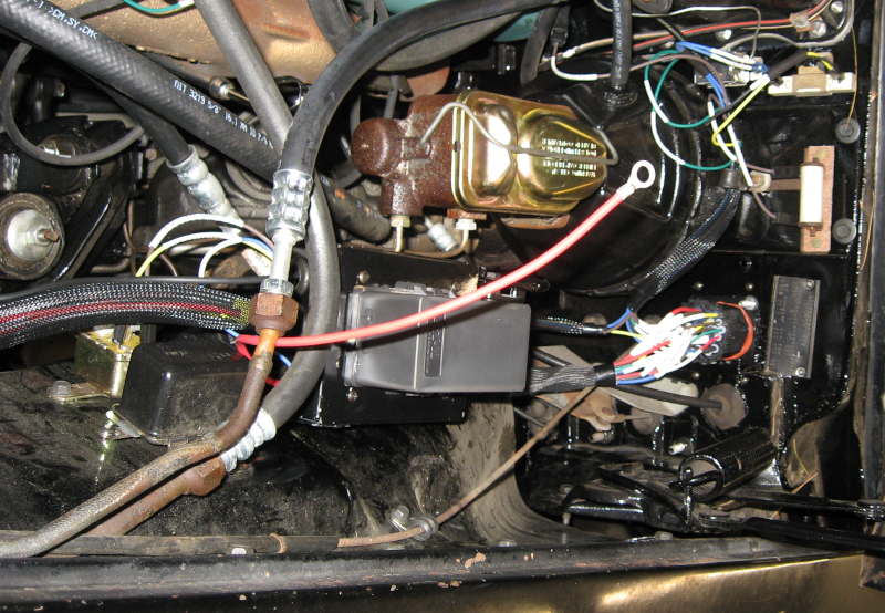
The whole bundle of new harness and old harness are picked up and the new fuse box is mounted in place. Go to connect the bulkhead connector:
And the wire bundle is 1″ too long. Perfect! Absolutely perfect! This is just the length needed to provide a little bit of give in the bundle so it can be arranged out of the way, makes it easy to connect, and isn’t long enough to cause other problems. And there was much rejoicing!
Remaining steps include finishing the headlights, turn signals, parking lights, horn and windshield washer. After that is wiring the engine, including ignition, HVAC, and sensors. Last is doing the new wiring for the Alternator.
Next: Electrical 7: Headlights
Hi! I like your guide! Have a question: you wrote that you use lower ga cabels than the original. I understand why. But wich dimension are you using for rewireing for a bulkhead connector and which for the fuse/relay-box and which for a new headlamps wireing? With best regards Laszlo G. from Sweden (Imperial LeBaron’63)
Laszlo,
You have excellent taste in cars!
If you haven’t seen it, this is discussed in more detail at https://www.imperialjourney.org/2021/08/09/electrical-9-up-gauging/.
I’m using 12ga for most things carrying power. In most cases this is more for minimizing voltage drop than for actual current carrying capacity. For low power circuits, like turn signals, 14ga. Signaling only, like oil pressure and temperature, 16ga.
Headlights are 12ga. For the last two feet, which goes into the headlight pods, I’m planning on dropping down to 14ga because of the small tube the wires go through. Hopefully the tube is large enough for this.. The headlight wiring will be finished after the car is painted, which should be this summer.
The fuse/relay box uses MetriPack 280 connectors, which are rated for 30 amps. The bulkhead uses WeatherPack connectors, which are rated for 20 amps, so there is no need to go larger than 12ga into the bulkhead.
I’m using 6ga for the battery to power bus connection on the fuse/relay box.
Does this help?
Thank you for your fine site! Oh yes! Your comments and helpfulnes is very valuable for me! I coming to follow your advices. I know, it’s alot of a jobb, but the result is worth it. I have a long way in front of me until the perfect car, ’cause I’m just beginning the car’s preservation for the future. My car is the one and only in Sweden. With a best regards Laszlo G.
Thx Russ! I’m in the beginning to start my blog, but I’m a rookie. Anyway, I have an own domain (but just now is my wife use it…) and my blog coming under an subdomain. Just now must I learn WordPress. Not so easy… Have a little patience, my blog is coming. Thanks for your support!
Laszlo,
Starting your restoration project is also a great time to start a blog (like this one!) to document and share your progress.
There have been a few times when I didn’t feel like I was making any progress and then looked back over this site and thought “OK, I’ve actually done quite a bit. I’m making real progress!”