
In the last article Electrical 9: Up Gauging we largely finished upgrading the Imperial wiring. But the story wasn’t done. Bypassing the ammeter leaves no way to know the state of the charging system, so I planned to add a voltmeter.
This led to buying a <$20 multifunction digital gauge that included a clock, inside and outside temperature, and a voltmeter. Trying this out on a test drive produced immediate concern – the voltmeter said 12.3V when the system should have been over 13 volts. This indicated that the system isn’t charging, and driving the car would just run down the battery. A deeper dive was clearly called for.
Time to grab the good multimeter and connect it to the battery. This showed 12.7V, a reasonable value. The cheap, straight from the Far East multifunction device was inaccurate – shocking! The next step was to fire up the engine. If the charging system was working the voltage at the battery should jump to 13.2-13.4V. With the engine running the voltage stayed absolutely flat – no change at all. Krud. The charging system was actually bad.
Three things could be bad: the voltage regulator, the alternator, or the wiring. And they were all new. In fact, the voltage regulator was an upgraded solid state regulator that should work better than the old electro-mechanical regulator.
Still, the symptoms looked like a voltage regulator. The fastest way to get a new one was through Amazon, so an order was placed. I still needed a voltmeter, so I also ordered a dual USB with voltmeter that plugs into the cigar lighter. The new regulator arrived, was installed, and no change. The new voltmeter seemed accurate when compared to the digital multimeter.
Again, krud. OK, check the alternator wiring against the service manual again. There are only three wires and it is straightforward; everything looks correct. OK, that leaves the alternator. While getting ready to order another new alternator (the alternator was replaced during the rebuild) I remembered that I had saved the old alternator. I was even able to find it. OK, install the old 35 amp alternator, verify that it works, and then order another 65 amp alternator.
Fire up the engine – and no change. Still no charging. Krud. The possibilities are two bad voltage regulators, two bad alternators, or bad wiring. I spent a couple of days checking everything – tracing the wiring, checking the wiring, jumpering around the wiring with direct connections, running various tests, and in general pounding my head against a brick wall.
While reading up on charging system tests for the 87th time I realized that I had done an alternator test wrong. The test is to connect the FLD (Field) terminal on the alternator directly to the positive post of the battery. If the alternator is good it will over-charge the battery, producing over 14V. You don’t want to do this for long, as it will destroy the battery and the alternator.
When I performed this test the first time I had left the wiring harness connected. This acted like a dead short, producing sparks and instantly heating my test wire. Thinking about it, this shouldn’t have happened. This time I disconnected the wiring harness from the alternator, connected a test wire, and started the engine.
With considerable fear I touched the test wire to the positive post of the battery – and nothing dramatic happened! OK, a good sign. Hold the test wire on the battery terminal and the voltage reading starts going up, quickly exceeding 13.6V and clearly charging the battery. Now this is a very good sign! It shows that the alternator is good, strongly suggests that the wiring is correct, and points a finger at the voltage regulator.
Next question: is the new 60 amp alternator also good? Time to re-install the new alternator and re-run the test. With the new more powerful alternator the voltage quickly exceeded 14V. With the alternator good and the wiring good, pretty much the only thing left is the voltage regulator.
Two bad voltage regulators? Shouldn’t happen. For the third voltage regulator I ordered a premium regulator from RockAuto. More expensive, but hopefully better quality.
When the third voltage regulator arrived I bench tested it with a regulated power supply. Unlike the other two voltage regulators, this one showed 12V on the output FLD terminal; the others showed 0V in this test. An encouraging sign, so time to install this regulator.
With the third voltage regulator installed I once again fired up the engine – and watched the digital multimeter rise to 13.3V! The charging system is working. And the USB/voltmeter in the cigar lighter is also showing 13.3V.
The only thing left was to confirm these results. The voltmeter showed a consistent 13.3-13.4V during a test drive, exactly what it should be.
This one had me tearing my hair out. I don’t expect to get two bad parts in a row – I don’t “expect” to get one bad part in a row! I learned more about testing alternators and voltage regulators, so should be able to figure out something like this much faster in the future. Another lesson is to order parts from reputable sources.
With the charging system working I can call the electrical upgrades done.
Update 1:
The next morning I headed out on a longer test drive. Immediately after starting the voltage went to 15.3V and the voltmeter started saying “tilt”. Not good – this looks like the voltage regulator is shorted out. Pulled the car back into the garage, hooked up the good multimeter, and it was reading 15.6V at idle. Since this will fry the battery, the alternator, and what is left of the voltage regulator I started troubleshooting the charging system (again).
The voltage then went to battery voltage, like it was before I installed this new regulator. I checked across the IGN and FLD terminals and it showed an open circuit. The regulator is dead.
What is going on here??? Three bad voltage regulators? Mentally going through everything I had done I began to question how I tested this regulator. I had hooked it up to a bench power supply which could have put up to 10 amps through the regulator. In fact, this was likely – one of the resistors on the voltage regulator got so hot from the test that I burned my hand when I picked it up. Could I have almost burned out the regulator, leaving it good enough to work initially but damaged enough to quickly die? Unfortunately this seems like a distinct possibility… It looks like the only thing to do is try another regulator.
Update 2:
The fourth voltage regulator arrived and I installed it. It looked perfect while running the engine briefly. So far so good… It is really hot this afternoon so I don’t feel like a longer test drive. Will try to get out tomorrow for a good run.
Update 3:
On the test drive the next day the voltage went back above 15V again. Krud.
Time for more research. A recommended upgrade is to go to a later model electronic voltage regulator which Chrysler used in the 1970’s-1990’s. This later model regulator works with the new style alternator I had purchased, so I went ahead and ordered one.
Update 4:
The new(est) voltage regulator arrived. It is wired differently than the older style voltage regulators, so I made a temporary test harness with the new wiring connections that would let me try it without making permanent changes to the existing wiring harness. With the test harness ready, I installed the new alternator and the new voltage regulator, connecting them with the test harness. After a careful review of the wiring I started the engine.
And watched the voltage immediately go to 17V-18V. Not Good! Quickly turn off the engine.
This is getting ridiculous! I’m getting frustrated and out of ideas. Back to the Internet for more research.
I found some articles that suggested this behavior could be caused by a short in the alternator field windings that control the output voltage. This can be tested by checking the resistance between the field terminals and the case of the alternator – this should be an open circuit with infinite resistance.
Get the alternator on the bench, dig out the multimeter, and start checking. Hmm, Field Terminal 1 to case is measuring 4 ohms. Field Terminal 2 to case is measuring 0.3 ohms. Could this be the problem all along – the new alternator is bad???
Time to order another new alternator. Might as well order another new voltage regulator while I’m at it. Just in case the alternator problem managed to fry the voltage regulator. Stay tuned for the next update!
Update 5:
I ordered the new alternator and voltage regulator on Wednesday; supposed to arrive next Tuesday. Then got the order confirmation with new shipping information – now next Friday. Bummer, I didn’t want to wait that long. Thursday (yesterday) I got a package delivery email – and the new parts were on my doorstep! One day shipping as a (pleasant) surprise.
There are some indications that I might have originally received a new style alternator that was internally configured for the old style voltage regulators. Chrysler alternators were mechanically compatible over about a 30 year period – they all just bolt in. The switch to new style voltage regulator occurred in 1970. To make sure everything was new style I ordered an alternator and voltage regulator for a 1972 Imperial.
Time to repeat this familiar drill: pull out the old alternator, install the new alternator. Pull out the old voltage regulator, install the new regulator. Connect the wiring, including the test harness for the new style voltage regulator. Double check the wiring. Hook up the multimeter to check voltage. Check the wiring again. Start the engine…
And the voltage looked good. Encouraging, but we’ve been here before. Back the car out of the shop and head out on a test drive. This time the voltage stayed rock steady on 14.5 volts! This is at the high end of the normal range, but it is within the normal range and is expected at startup. Over a 30 mile test drive the voltage dropped to 14.4 volts and stayed there. When idling it would drop to 14.2-14.3 volts.
Things are looking good – this is exactly where the voltage should be. The next step is to do a permanent mount for the new voltage regulator and then replace the test harness with permanent wiring. Followed by another test run! Not that I’m paranoid or anything… Actually, at this point, I AM paranoid about the alternator and voltage regulator!
It looks like the underlying problem was a bad 60 amp alternator. This might have killed the voltage regulators, or it could have been something I did.
The engine is hot after the test drive so I will just put this job off until Monday.
Update 6: Success!
The final step was to install the voltage regulator in its final position and replace the test harness with production wiring.
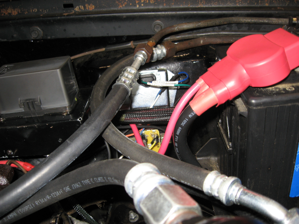
As seen in this picture there is little room for the voltage regulator and poor access. Despite this I was able to locate it and drill new mounting holes. I really need to get a right angle drill. And smaller hands…
The new voltage regulator requires two wires. I really didn’t want to run another wire – adding wires to a sleeved harness is a lot of work. The new voltage regulator doesn’t have the dedicated ground wire that the old one does – so why not repurpose the old ground wire as the new field wire? This simply required putting new terminals on each end of the wire – along with updating the labels on the wire so I won’t confuse myself in the future.
To ensure that the voltage regulator is well grounded I added a new ground wire from the updated chassis ground system to the case of the voltage regulator – this is the same ground that the headlights are using. I checked the grounding of the alternator to chassis ground and it was good, around 0.3 ohms.
With everything connected and the wiring double checked it was time for the first moment of truth. Fire up the engine and check the voltage. 14.5V-14.6V – just a touch high, but within specs.
I’ve been here before, so on to the real test – the test drive! After a good test drive, including Interstate driving, the voltage registered a steady 14.4V-14.5V. Again, on the high side but within specs.
I’m declaring success and moving on to the next project.
Next electrical article: Electrical 11: Connections Evolved
Next article: I take the Imperial to my First Cruise Night!