
The last electrical article looked at dash lighting in Electrical 12: Dash It All!. It is now time to deal with a sticky situation – specifically, power windows that stick going up and down.
Power windows are the among the worst cases for old car electrics – the motors require high amperage and are fed through long wires and small switches. Over time the window mechanisms become harder to operate, requiring even more power from the motors. At the same time the wiring degrades, reducing voltage available to the motor and making it work even harder. The result is that power windows simply don’t work well on old cars – when they work at all.
In my case one of the windows (drivers door, of course…) doesn’t work at all, two windows barely work, and the fourth window is slow and doesn’t always go all of the way up.
Part of the work on the doors includes cleaning and lubricating the window mechanisms. This certainly helps, but doesn’t go far enough to solve the problem.
Really solving the problem requires completely replacing the existing power window wiring with something that can handle the power requirements.
Relays will be used to provide power directly to the window motor – basically the same thing that was done with the headlights when they were upgraded. The existing switches still control the windows. But instead of handling the 20-30 amps that the motor draws, the switches will now trigger the relays and only have to handle less than 0.1 amps. The existing wiring and switches are easily able to handle 0.1 amps.
The window motor requires two relays – one for up and one for down – which makes the wiring somewhat more complex than the headlights.
Power for the relays will be provided by a new dedicated 12 gauge power line that is run directly from the relays to the fuse box. Power will now come from a shorter run of heavier gauge new wiring – the motor will now get full voltage and full power.
Since I’m paranoid – in other words, I have experience… – the relay upgrade will be done as a series of incremental steps with testing at each step. Thus the first step is to build a test harness to allow testing the window motors outside of the existing window wiring. This test harness will go through a series of modifications and upgrades as the build proceeds.
The initial test harness was simply two wires connected to the battery. There are two wires to the motor – I was pretty sure that the motor case is ground, and you apply +12V to one wire to go up and +12V to the other wire to go down. But it could also be reversing plus and minus between the two wires for up and down.
With the two wires connected to the to the battery, the negative wire was held against the motor case and the +12V wire was applied to one of the wires to the motor – and the window went down! +12V was applied to the other wire and the window went up. OK, motor wiring is confirmed.
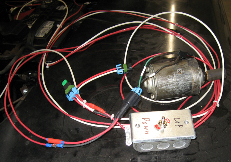
Next a two way switch was added to the test harness. Technically this was a dual pole/dual throw momentary contact switch, also known as DPDT momentary contact. This allowed using the switch to control up and down on the motor. Connectors that mated with the motor were added. The test harness is long enough to reach from the battery to each door and to the workbench, making it easy to operate the windows either on the car or on the bench. This was convenient since you need to move the windows up and down to remove the glass. As previously mentioned I’m paranoid, so a fuse was also added.
Since the test harness will also be used to implement the new dedicated power wiring, a matching power connector was added. The test harness can be used to directly power and control the window motor in the car or on the workbench as well as provide power to the relays.
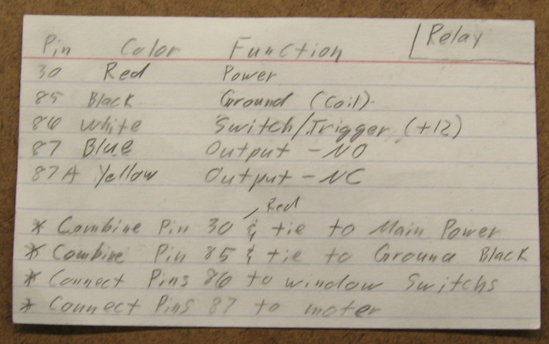
With motor operation verified and the test harness ready to go it was time to build the relay setup. The first step was to lay out the design on paper, double check it, and determine how to connect the relay wires. I’m using Bosch style relays which have five wires – trigger/source, ground, power in, power out normally open and power out normally closed. Since the relay should provide power when the switch is turned on the normally open (NO) output is used and the normally closed (NC) output was sealed off.
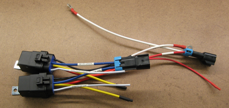
The relays I’m using came with sealed sockets and pigtails – this makes it easy to wire them up. The good news is that the pigtail wires are color coded. The bad news is that the color coding didn’t comply with standards… Notes that include pin number, color, function, and wiring instructions kept me from becoming excessively confused when making the four relay packs (one for each window).
I wired up the relays on the bench – it is much easier to work on the bench, and it gave me the chance to double check everything before installing. Note the labels on the wires – this minimizes mistakes and makes it much easier to troubleshoot in the future.
The test harness and a voltmeter allowed complete testing on the bench. No mistakes were found in the wiring. OK, OK – no mistakes were found when the relay packs were ready to install in the doors…
The window motor was originally grounded through the door skin. Since it is very little additional work to run two wires instead of the planned one wire for power, a dedicated 12 gauge ground wire was added. This ground will tie directly into the upgraded grounding system under the dash and is bolted to the power window mechanism frame which is connected directly to the motor. This also provides a convenient high quality ground point for any other potential electrics in the door.
The new power and ground wires are connected to the relays using a waterproof Metri Pack 280 connector. The relays are sealed, and all wiring connections are sealed with marine grade heat shrink tubing – the result is that there shouldn’t be any corrosion in the power window system.
The motor originally used non-sealed Packard 56 connectors, which I replaced with more of the Metri Pack 280 connectors. When I cut the old connectors off and stripped the insulation, the wires were solid black with corrosion. Sandpaper and electrical contact cleaner cleaned up the wire ends and the new sealed connectors should prevent more corrosion in the future.
The test harness was plugged in to provide temporary power to the relays and window operation tested. It worked!
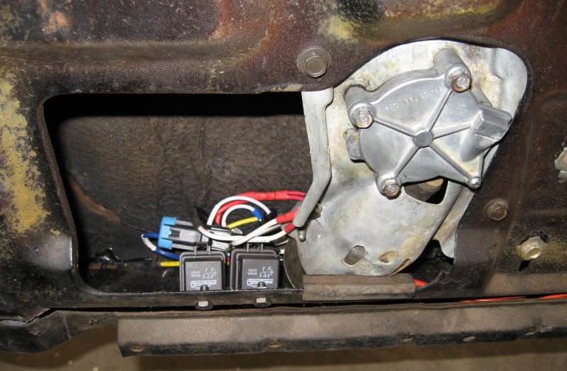
With everything ready to go I spent an hour or so making a bracket to mount the relays. I then tested window operation and watched the window hit the relays as it neared the bottom position. Actually I stopped the window just before it hit the relays. I’m getting paranoid about that sort of thing…
Studying the situation more, I decided that the relays could be mounted directly to the inner door skin. The relays were mounted in this new position, the window run down, and nothing hit. OK, one more problem solved!
The window now goes up and down smoothly. It will need to be adjusted to fit the new weatherstrip I’m installing. This will probably be a nightmare; if it is I will do a post.
This process will be repeated for the other three doors.
I also need to finish connecting the new power wiring. As I do each door I’m running the new power and ground wires up to under the dash. The next to last step will be to connect all of the new power and ground wires and splice into the existing power window feed from the under hood fuse box.
The last step is to enjoy the new smoothly operating and reliable power windows!
Next electrical: Electrical 14: MeterMatch.
Next: battling rust in Door Three “Delights”.