
Previous Electrical article: Electrical 14: MeterMatch
While looking over the electrical posts I realized that I haven’t mentioned one of the most important resources for working on wiring – the wiring diagrams contained in the factory service manual. These are absolutely vital to working on the electrical system!
Intimidating at first glance, a wiring diagram is actually your roadmap to success. They provide a complete picture of every wire in the car from battery to final ground, including all connections, switches, junctions, and plugs.
Consider this wiring diagram for the engine bay of a 1963 Imperial:
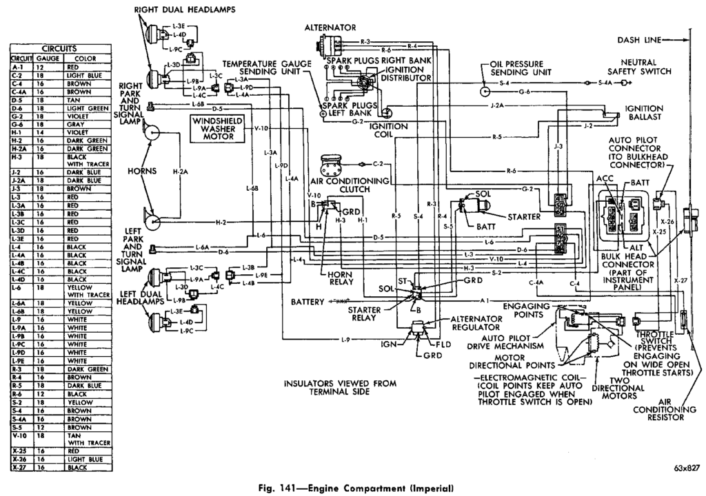
This diagram shows everything from the headlights on the front of the car to the bulkhead connector that goes through the firewall into the passenger cabin. It shows all the wires and where they are connected. Each circuit is labeled, such as A-1, H-3, or L-9C.
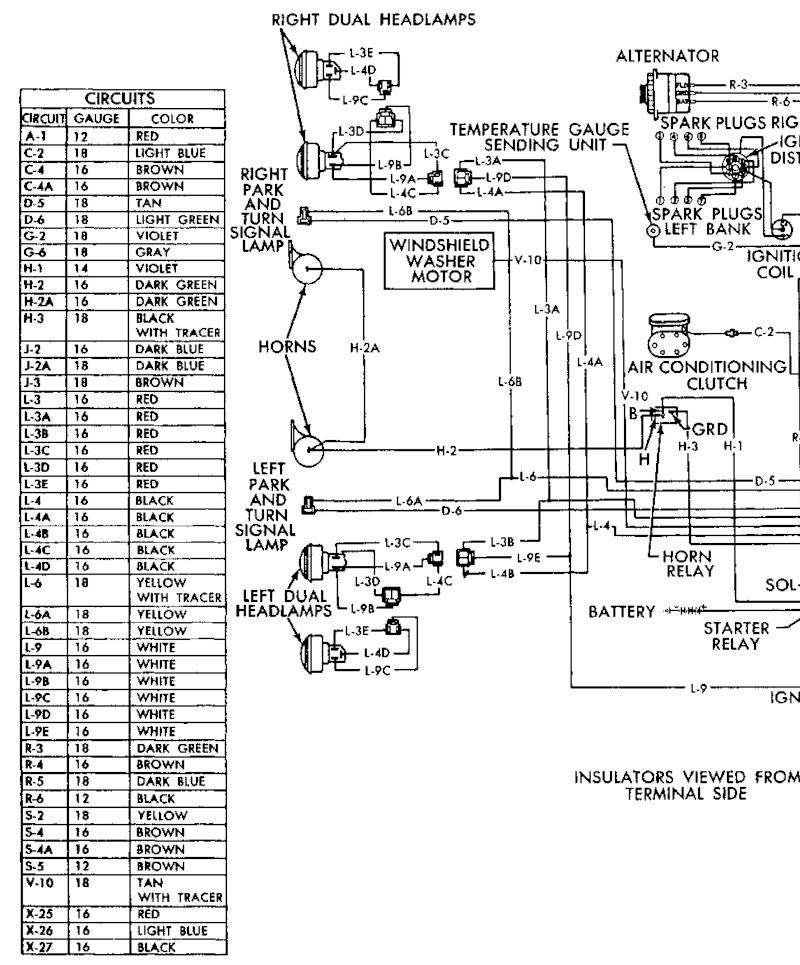
The chart on the left side of the diagram lists each circuit, the wire size, and wire color. Looking at the bottom right corner of the wiring diagram we can tell that circuit L-9C is a 16ga white wire that goes to the left most headlight. Tracing this across the diagram we can tell that L-9C goes to a 3-way connector, where is is connected to L-9E. L9E then joins with L-9D and L9. L-9D goes to the right side headlights and L-9 is grounded at the voltage regulator ground point. All of the L-9 wires are 16ga white wires. OK, L-9 is the headlight ground.
Right above L-9E is L-4D. Here is where we can apply some outside knowledge. We know that the outermost right and left headlights are combination Hi beam and Lo beam headlights, while the inner two headlights are Hi beam only. The wire that goes to all four headlights is Hi beam and the wire that only goes to two headlights is the Lo beam. Careful examination shows that L-3 goes to all four headlights, so it is the Hi beam. L-4 is the Lo beam.
Based on this we know that circuit L-4 is a black 16ga wire for Lo beam headlights and L-9 is a red 16ga wire for Hi beam headlight. Tracing the Lo beam wire, L-4D connects to L-4C which connects to L-4B which joins with L-4. L-4 then goes to Pin 1 on the large bulkhead connector on the firewall. If we go to the cabin wiring diagram we will discover that this wire goes to the Hi/Lo switch, the headlight switch, and ultimately a power source.
The same approach works for the parking light and turn signal. Again, we have background knowledge: the bulb for this grounds through the bulb base, directly into the socket and ultimately the car body, so all wires going into the socket are power. Parking lights are common, and will have a common power wire. Left and right turn signals are independent, and will have separate wires. Circuit L-6 is common to both sides, so it is the parking light. Looking at the left side of the car, L-6A is an 18ga yellow wire that joins to L-6A and L-6. L-6 goes to pin 6 on the large bulkhead connector. Inside the car it connects to the headlight switch.
This means that D-6, an 18ga light green wire that goes to pin 8 on the large bulkhead connector is the left turn signal. Circuit D-5, an 18ga tan wire going to pin 5 on the large bulkhead connector, is the right turn signal.
Because I’m easily confused I clearly label both ends of each wire when I’m working on a wiring harness with both the circuit number and the function – for example, “L-4D Left Headlight Lo Beam” or “L-3C Left Inner Headlight Hi Beam”. This makes life much simpler the next time I’m working on the electrical system – both for the function of the circuit as well as the circuit number for tracing across the wiring diagram.
This wiring diagram is actually fairly simple – others get much more complex. I find it useful to copy or print out wiring diagrams and trace circuits I need to follow with a colored highlighter pen. This makes it “easier” to follow a circuit end to end (or middle to middle), as well as keep track of multiple circuits. You don’t want to do this in the actual factory service manual since the page will become unreadable after tracing a few circuits. It is also easier to take one or two sheets of paper into the car while you are working on it than to drag the large factory service manual around. As well as making it easier to take notes while you are working.
With a set of wiring diagrams, a multimeter, and some patience and persistence you can tame the dragon of electrical wiring!
At least on old cars – modern cars use communications networks. These networks start with CANbus (Car Area Network bus) and are migrating to Automotive Ethernet. Yes, a variation of the same networking protocol used for computers! I stay far away from the new cars; these old cars are enough of a challenge.