
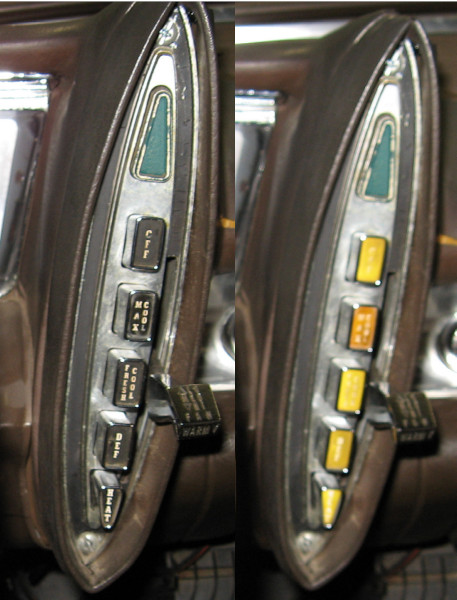
The Imperial uses electroluminescent lighting for the instrument panel, heater controls and transmission controls. The heater and transmission use plastic pushbuttons with a panel beside them to light the button caps. Unfortunately these panels degrade over time and now barely illuminate the push buttons.
Further, after re-connecting the panel for the heater controls the overall illumination for the instruments is excessively dim – and I’m someone who turns the instrument brightness down to where they are barely legible!
While contemplating this situation inspiration hit with an audible thud – “hey, don’t they make LED panels? And LED dimmers?”
A quick search turned up a set of 2″ x 2″ LED panels. Available in packages of 10 for $15. And dimmers for LEDs are around $10. OK, this is cost effective! At this price I can afford to experiment.
So I ordered a set and tried them. The work great! Amazingly bright on full power yet able to be dimmed to almost nothing. This should work!
That was two years ago. Getting the heater control out is such a miserable job that I put this project on the back burner until I had another reason to pull the heater control. That day finally arrived – I’ll make another post on that little incident..
With the heater control on the bench I discovered that three of the LED panels nicely covered the illumination plate. And three panels work just as well as a single panel on the dimmer.
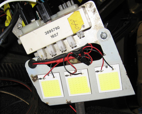
With the heater control installed back in the dash (first of many times. sigh.) it was time to connect the LEDs to the dimmer. And to connect the dimmer to a power supply.
It would be really nice to have this in the headlight circuit so the the heater lights are turned on and off with the rest of the dash lights. But all of the instrument lights are plugged into the back of the instrument panel and totally buried. The power for the original electroluminescent panel is 200V AC – won’t work. I had been postponing this part of the project for multiple reasons!
Hmm, there is the unused connector for the radio backlight… (The radio is another “interesting” story that I’m trying to block out of my memory.) It has power. And dimming. I wonder if the LED and dimmer work with less than 12V input power? Time to make a temporary connection and find out.
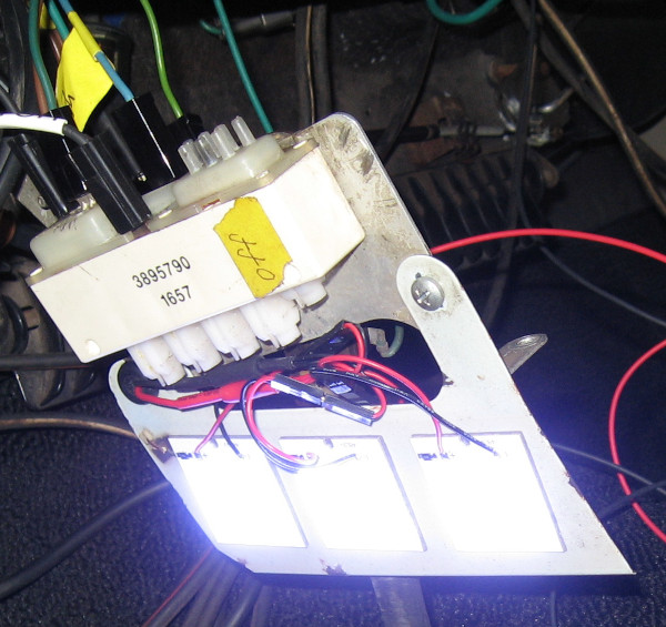
Well – would you look at that! It actually works quite well with the dash lights turned down low! The max brightness is less than you get with the full 12V, but even with the reduced input voltage I need to dial it way down.
I’m going to declare this one a success!
Previous Electrical Post: Electrical 15: Factory Wiring Diagrams