
I recently made a couple of parts on the milling machine. The first was for mounting a Quick Change Tool Post (QCTP) on the lathe. A QCTP makes it quick and easy to change cutting tools on a lathe and is a big improvement in ease of use. Since each lathe is different they ship with a block of steel that you machine down into a T-nut that fits your lathe. Since I could get the measurements off of the T-nut for the old tool post this was fairly straightforward. Took a few hours, but the QCTP is firmly mounted on the lathe.
The second part was a custom latch for the screen door on our 3 Season Room. This was whittled out of a block of steel and is holding the door firmly in place. Most of the work on the latch was done using a 2″ face mill. I wasn’t sure if the mill had enough power and rigidity to handle this large a cutter, but it did fine. But I could tell that the back of the cutter was digging into the part during certain cuts. The milling machine was clearly out of alighnment.
I knew that the mill needed a good tuneup. Order the parts needed, find some time, and get after it!
The cord for the machine was much too long – about 20 feet – was in poor condition and the plug was bad. Replace the plug, shorten the cord to roughly 6′, and add some heat shrink tubing over the worst remaining area. I really should replace the entire cord at some point.
The mill was wobbling on its base. I had wedged a shim under one of the legs, but this was a temporary expedient. A better solution was a set of adjustable caster feet. These have a caster that lets you move the mill around and a set of rubber feet that can be screwed down to hold the mill in place and level it against the floor.
Once again the trusty engine hoist raised the mill so that the caster feet could be installed. Jockey the mill into position where I want it, screw down the feet, and the mill is ready for use.
Next, the beds were stiff and difficult to move when turning the handwheels. I suspected that the ways were dry, so get a good coat of way oil on them and work them back and forth. Better, but not good enough.
Machine tools use wedge shape pieces of metal called gibs to fill gaps in the machine and allow adjustment. These are adjustable – you want them just tight enough to avoid movement of the bed and just loose enough to allow the handwheels to turn smoothly. Too tight and you can lock up the machine. Too loose and you get chatter and really poor accuracy.
I adjusted the gibs just enough to allow smooth operation of the handwheels. It feels a lot better – I now need to cut some test parts and see if it is tight enough to maintain accuracy and good surface finish.
To cut accurately the head of the milling machine – the part that holds the cutter – needs to be absolutely perpendicular to the bed. If it isn’t all sorts of bad things happen. Adjusting the mill so that the head is perpendicular to the bed is called tramming the mill. And it is generally conceded to be a tedious job. And a necessary one that is often put off too long.
There are several ways to tram a mill. A common one is to mount a dial indicator indicator in the head and check the height of the bed in several places. If the mill is properly trammed the indicator will read 0 everywhere it is placed on the bed. The dial indicator I have measures to 0.001″ and you can estimate measurements to 0.00025″
The first step is to take the machinist vise off of the mill and thoroughly clean the bed with a scotchbrite pad. The bed just had some surface rust – it cleaned up nicely and is solid. There aren’t any serious gouges or marks in the bed, so it looks like it hasn’t been abused. Good news! Overall the mill seems to be in excellent shape with little wear.
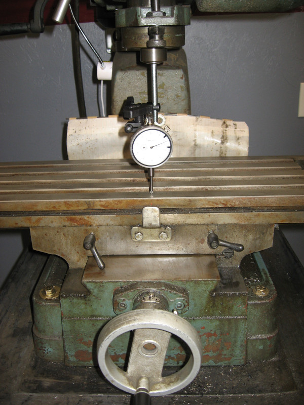
Initial results? Side to side was off about 0.001″. Not too bad; I can live with that. Front to back, on the other hand, was off 0.006″. Yeah, that’s completely horrible and would explain what I was seeing on the latch.
Big mills are adjustable. They have mechanisms to rotate the head left and right and front to back. Tramming them is tedious but straightforward.
Small mills, like mine, have no mechanism for adjustment. The only way to adjust them is to loosen the four bolts holding the column to the base and insert shims under each corner. Front to back and side to side are adjusted at the same time and interact with each other. You hold one corner fixed and shim the other three until everything is in alignment.
Since my memory is shot, get a piece of paper and record the measurements from the dial indicator for front to back and side to side and the thickness of the shims under each corner of the column. Study these numbers and estimate what shim needed under each corner. Loosen the four bolts on the column, insert the proper shims under each corner, and tighten the bolts down again.
Take a new set of measurements with the dial indicator. If close enough to zero, done. Otherwise repeat the process.
I repeated the process. More than a dozen times over four hours. Tedious. Very tedious!
I finally got the error down to a little under 0.001″ both front to back and side to side. Serious machinists would sneer at this. With more iterations even I could do better. But this is pretty good for a small hobby mill and a machinist with my (lack of) skills.
With the mill trammed the last step was to mount the vise and adjust it so that it is parallel to the bed. This is straightforward with the dial indicator and is actually done fairly quickly.
I need to machine something to check it out. Time to come up with another project!