
I’m moderately proud of figuring out a way to use modern LED technology to replace the 60 year old electroluminescent technology in the HVAC (Heater Ventilation and Air Conditioning) controls. On the other hand, the mounting for the dimmer control for this was not one of my prouder moments…
I had simply zip tied the control module under the dash. In a visible location. Because there wasn’t an hidden place to mount easily it. As I’ve mentioned, for such a large car there is very little space in many areas. Like under the dash.
With the rest of the interior coming together and looking good something had to be done about the HVAC LED dimmer.
When starting the HVAC lighting project I actually ordered two dimmers: a packaged, ready to use unit, and a more compact modular unit that consisted of a 1″x1″ circuit board, connecting cables, and rotary control knob. While I wanted to use the modular unit it was easier to use the packaged unit for prototyping.
The biggest problem, of course, was finding the modular unit. After extensive searching I found it just where it should be – in the box with the rest of the LED components…
You know that old saying if the only tool you have is a hammer, every problem looks like a nail? And my personal favorite: a big enough hammer can drive any screw.
Well, with a 3D printer suddenly any problem looks like something that can be solved with a custom part!
Studying the underside of the dash it looked like the perfect solution would be to extend the custom bracket holding the updated fusebox. I had been wanting to do this anyway – this was the first fusebox bracket I did and the cutout for the fusebox itself had been gouged to “close enough” size with hand tools. Later brackets used laser cut parts from SendCutSend which are a much better fit. And I had an extra blank.
OK, let’s get this party started!
First of all, I wanted the LED to be a bit dimmer than the lowest setting on the dimmer control. I noticed that changing the brightness of the dash lights also dimmed the HVAC LED. Putting on the Electrical Engineer hat that I don’t have, this implies that I can make the dimmer dimmer by adding a resistor to the power supply wire. A 2 ohm or 5 ohm resistor should do the trick. Time to head to Amazon!
Although the LEDs don’t draw much power I was concerned that the widely available (and cheap) 1/2 watt resistors wouldn’t be enough. A bit of searching turned up an assortment pack of 5 watt resistors at a semi-reasonable price.
Without being sure what was needed it made sense to test the resistor circuit before wiring it permanently. Easy enough to do – grab a couple of jumper wires with alligator clips. One wire from power to resistor and the second from resistor to dimmer. Hook it up, wait for night, turn off the workshop lights, wait for darkness, and verify that I had the correct value.
Hmm, not much difference in brightness with the 2.2 ohm… OK, the next size up is 3.3 ohms Still not enough change. Well this is why I got the assortment pack! Grab the 10 ohm. Better, but still not quite what I wanted. 22 ohm? 47 ohm? Finally at 100 ohm it was close to the (lack of) brightness I was looking for.
This was much more resistance than I expected – glad I experimented first! Discussing this later with a friend who is a real electrical engineer, he told me that he sometimes has to go as high as 500,000 ohms in similar circuits. Huh, learn something new every day! Guess I should have tried 1,000 ohm and 10,000 ohm resistors while I was at it.
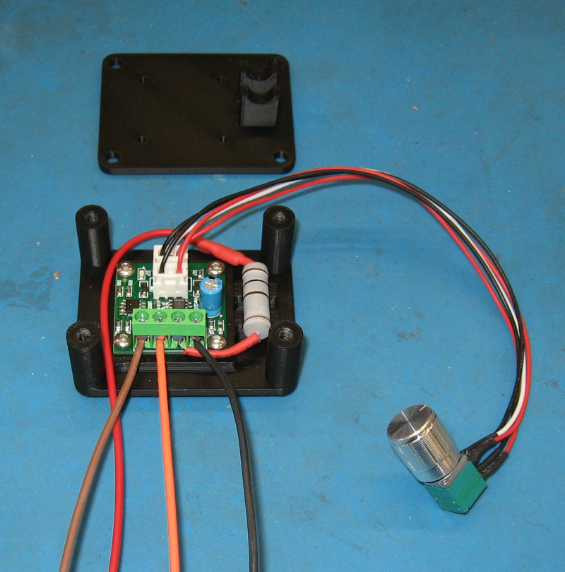
Now to design the case to hold all of the electrical components. Complex designs are basically a bunch of simple designs connected together. In this case I needed a mount for the circuit board, a holder for the resistor, a baseplate for these, a top plate to provide protection, and four columns to tie everything together.
And that is exactly how I designed it: a mounting plate for the circuit board that picked up the screw holes in the circuit board and was extruded to provide space for the components sticking out of the circuit board. A pair of rectangular pillars with holes for the tubular resistor. These were split in half forming a saddle so that the resistor could be inserted and then firmly clamped in place. Next was the baseplate with both of the mounts integrated into it and round columns at each corner. Finally, a top plate that screwed to the columns and which included the top half of the resistor mount.
Print it out, test fit everything together…. And as usual discover a few things that needed to be tweaked. Absolutely normal. The amazing thing about CAD and 3D printing is that you can do this quickly, easily, and cheaply. For example, these parts used about $0.25 of material.
With the housing done, turn to the bracket. Remove the original bracket from under the dash and use it as a reference. Decide how much it needs to be extended to support the dimmer box and dimmer knob. Mark this extension as well as the bends for bolting the bracket to the dash on the fuse box bracket panel.
Drilling the mounting holes for the dimmer box was easy – take the top plate and use a transfer punch to mark the center of each mounting hole and then drill them. Determine where the control knob should go and drill a hole for it. Drill a hole for the mounting bolt that will secure the bracket to the bottom of the dash.
Bend the bracket so it will mount properly and weld a nut to it. With an earlier version of the bracket I used a separate nut – trying to hold the bracket and loose nut in position while starting a bolt proved to be a nightmare. Test fit the bracket. It fits, so hit it with a couple of coats of paint.
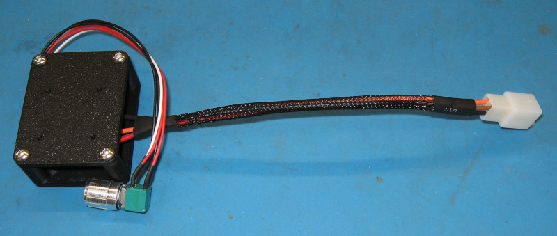
Really should clean up the dimmer box before final mounting. There are four wires on the dimmer – two for power in and two going to the LEDs. Add these wires, sleeve them, and add a connector to the end. Add a matching connector to the wires in the dash. This will simplify installation and any future maintenance on the dimmer circuit.
OK, to be perfectly honest, I’m turning into an electrical snob as I learn more about wiring.
Bolt the dimmer box to the bracket, mount the control knob in its hole, and we’re finally ready for installation. I had an extra fusebox from another project, so I temporarily mounted it in the bracket to make sure everything fit.
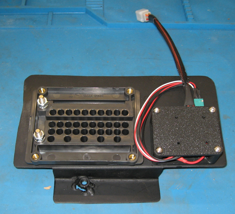
Moment of truth time: slip the bracket under the dash, position the fusebox in its cutout, and bolt the assembly to the dash. With the mounting bolt secure, run in the four machine screws that fasten the fusebox to the bracket. Plug in the connector for the dimmer module.
Fortunately it was late enough that it was dark. Turn off the workshop lights, turn on the Imperial headlights, and adjust the dimmer knob. Everything worked!
And there was much rejoicing!
The dimmer module is now securely mounted, completely hidden under the dash, yet the control knob can be easily reached to adjust brightness. I’m declaring this a success and moving on to the next project.