In the previous article Electrical 2: Grounded we started the electrical work with perhaps the most overlooked part of automotive wiring.
Perhaps the greatest weakness in the electrical system of older cars is the bulkhead connector that connects the engine compartment to the rest of the car. Unlike modern bulkhead connectors, these old connectors were not sealed – this leads to corrosion in the connector which increases resistance, reduces voltage, and leads to a wide range of problems.
The problem is made even worse by undersized wiring which is also corroding and likely to have cracking insulation.


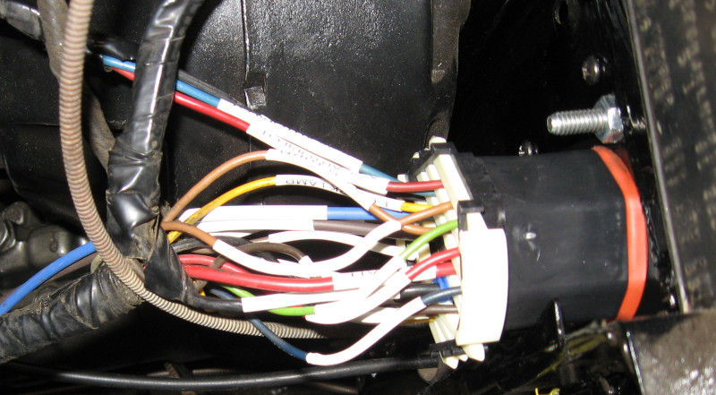
In this second picture you can see the corrosion inside the bulkhead connector. Surprisingly the wiring insulation is still in good shape. The red and black wires are power and ground and are 12ga – this is marginal for today’s electrical loads.
Modern cars use waterproof sealed electrical connections. Examples of this include Weather-Pack, Metri-Pack, and Deutsch. I decided to use Metri-Pack and Weather-Pack which are widely available and “reasonable” cost.
Weather-Pack connectors are rated at 20 amps. Different models of Metri-Pack are rated at 14 to 60 amps per connector; I’m using the Metri-Pack 280 family, which is rated at 30 amps per connector. Unfortunately Metri-Pack is not available in high pin count bulkhead connectors.
The best choice is the Weather-Pack 22 Position Bulkhead Connector. This is a sealed bulkhead connector that supports 22 connections. Using an adapter plate it fits into the same space as the factory bulkhead connector, meaning that it isn’t necessary to cut the firewall.

As mentioned, the Weather-Pack connections are only good for 20 amps. I really need more power than this. The factory bulkhead connector only has 18 connections – this means 4 connections are available for other use.
I will be using two of these to provide switched power and two to provide unswitched. Combined with the factory circuits (one for switched and one for unswitched) this will give me three 20 amp circuits – which provides 60 amps total power delivery – for both switched and unswitched power.
Installing the Weather-Pack bulkhead connector was a tedious process. For each wire:
- Identify wire and circuit. Cross check terminal location and wire color against factory service manual.
- Double check identity of wire and circuit.
- Create 2 labels for wire. This identifies the circuit and use.
- Cut wire from the old bulkhead connector.
- Slip label over wire.
- Slip Weather-Pack seal over wire.
- Strip end of wire.
- Crimp Weather-Pack terminal onto wire.
- Use heat gun to shrink the label.
- Move on to next wire
At the end of this process you have 44 wires ready to plug into the connector shells. It is critical to get the same wire plugged into both sides of the connector – crossing wires is a bad thing. To make it more entertaining the two halves of the connector are done separately and are mirror images of each other.
The way to avoid problems is to have a map of the connectors showing where each wire goes. A spreadsheet is a surprisingly good tool for this.
Start by listing all of the circuits on the factory bulkhead connector. Include connector pin location, circuit number, wire color, and wire size. Also include a description of the circuit. Looking forward, plan which pin location on the Weather-Pack connector will be used.

Spreadsheets are square and the Weather-Pack bulkhead connector is round. The answer is to visually map spreadsheet cells to the round bulkhead. In fact, do this twice – once for both male and female connectors.

This map shows the location of each pin and the identity of each pin – each pin is identified by a letter which is the same on both the male and female connectors. Each wire is labled with the circuit number and description.
The process is to start at the bottom of the connector, find the wire that goes in that location, and insert it into the connector until it locks into place. Then find the next wire and insert it. Double check to ensure that you have the right wire and the right pin location. Continue this process until you have plugged in all of the wires.
After completing the first connector do the same thing on the other connector – making sure you are using the correct diagram, male or female!
At the end of this process you will have a new sealed bulkhead connector installed in the firewall with all circuits labeled.