While sewing is needed for the seats and door panels there are a couple of trim pieces that don’t require sewing – I can start with those. The back seat has a trim panel that goes between the seat and the side of the car. These will be a great place to start.
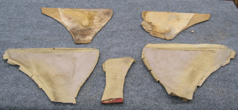
These trim panels were not installed. I found parts of these panels in the trunk of the car. They were in terrible shape – worn, dirty, water damaged, and torn in half. Complete replacement was required!
Original Trim Pieces – the parts I could find
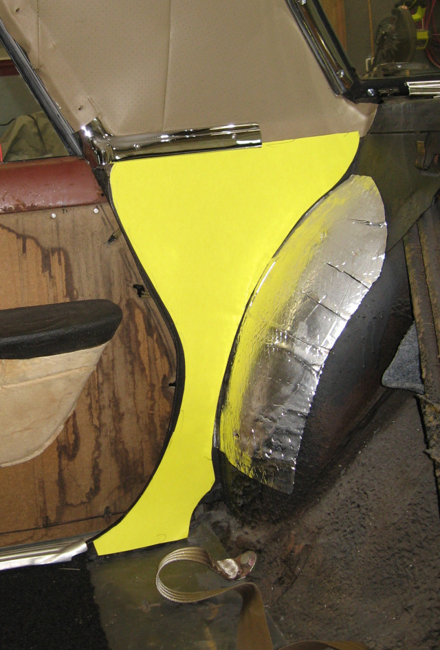
Time for some CAD – cardboard aided design. A cardboard template was trimmed and adjusted until it fit the space.
Template for trim piece
Once the cardboard template was fitted the outline was traced onto a piece of 1/8″ hardboard and cut out.
The next step was to cover it with 1/4″ fabric backed foam and some of the JoAnn test vinyl, stretch the vinyl, and staple to the back. The result was OK, but had some wrinkles and was a bit thick. But it did fit properly.
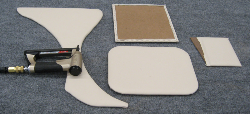
Since I now had the real fabric I started on the actual panel. Once again, a piece of 1/8″ hardboard was cut out. This time I applied spray adhesive to the hardboard and a piece of 1/4″ fabric backed foam and secured the foam to the hardboard. I then trimmed the form to the hardboard so that the foam didn’t wrap around the edge.
The next step was to cut out a piece of the real vinyl – SoftSeat Light Cashmere – about 3/4″ larger than the template. Spray adhesive on the foam and vinyl, carefully position the vinyl, and apply the vinyl to the foam. After it was in the right position I rolled the vinyl to the foam to secure it in place.
I then flipped the panel over and started notching the vinyl close to the edge – but not so close that the cuts would show from the front or side. Starting from the middle of an edge the vinyl was carefully stretched over the back and stapled in place.
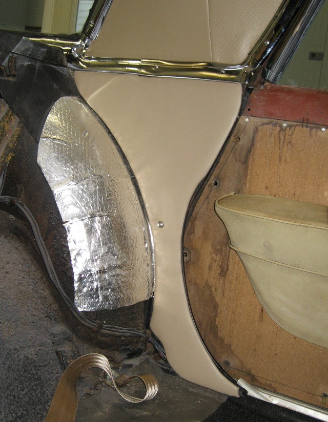
The end result was this complex shape with no wrinkles in the vinyl and good definition along the edges. I’m rather proud of the result! With the first piece a success, the second trim panel was made and installed.
Rear Seat Side Trim Panel Installed
If only the rest of the interior could go this smoothly! I rate the chances of that happening as somewhere between zero and zero, but I’m an optimist…
With the shop and materials for upholstery work coming together I ran out of room for stalling on what material to use. Time to make some decisions and place an order.
The first big question was leather or vinyl? Leather is the leader for luxury – and is by far the most expensive option. Vinyl is good, widely used, and can be relatively inexpensive. The deciding factor was that I’m going to be making mistakes. I expect to make and re-make things several times while learning how to do this upholstery thing. It would drive me nuts to destroy or waste several hundreds of dollars of leather! So, vinyl it is.
I couldn’t find a local place stocking automotive fabrics, so it was on to the Internet to find out what was available online. Searching quickly turned up several suppliers. Your Auto Trim Store seemed to have what I was looking for, so I ordered several sample kits for different types and colors of automotive vinyl fabric as well as samples of foam backing.
With a sample kit you can see and feel the actual fabric you will be using. Going through the sample kits I decided that I liked the texture and feel of SoftSeat brand automotive vinyl. SoftSeat is available in both solid and perforated, allowing you to build more comfortable seats. Softseat also had a good match for the factory interior color.
I (of course) had trouble deciding what color to choose. A black car with black interior is classic. A black car with white interior is really sharp – and a stain magnet. Red? Kind of dramatic, but works with black. Rose is a bit more subtle but could look really rich. Gray? I like gray, so this could work. Hmm, some shades of blue work well with black; maybe teal or turquoise? Or maybe go with something really dramatic, like screaming banana yellow!
After enjoying prolonged indecision I finally decided to go with the factory color – a sort of cream. The existing seats had been re-upholstered at some point were a completely different color, but the door cards were still the factory color. Well, a dirty 60 year old version of the factory color… Further, the headliner was close to the factory color. Also, the dash is brown. Changing the color of the dash and the plastic dash pad would be a major project.
With the SoftSeat sample ring in the car I determined that SoftSeat Light Cashmere was a good match for the factory color. The plan was to use solid for most of the seats with perforated inserts where you will be sitting. I find that having contrasting inserts in seats provides a richer appearance, so I decided to also order SoftSeat Medium Prairie Tan for the inserts.
With colors chosen the next question was quantity. Automotive Vinyl is typically around 54″ wide and is ordered by the yard. I did a rough calculation of how much material each part of the seats, door panels, and trim would require, allowed plenty of allowance for cutting the pieces out of the roll of fabric, and then added another 25% for safety and mistakes.
To give myself flexibility I planned on getting enough Light Cashmere to do everything plus enough Medium Prairie Tan to do the inserts.
At this point She Who Must Be Obeyed pointed out the importance of getting everything you need at the same time. If you don’t have enough fabric and have to order more, there is a good chance the new order will be from a different dye batch and the colors won’t match. OK, add another 25% or so to the order. Realistically I probably have enough vinyl to do two complete cars.
It turns out that ordering automotive vinyl online is much cheaper than I expected. The SoftSeat vinyl is under $14 a yard for solid and under $19 a yard for perforated! The initial order I put together was under $600; going in I expected materials to cost over $2,000! Hmm, at this price might as well add another yard or two of each vinyl…
In addition to the vinyl I also needed foam: 1/4″ fabric backed foam for most of the trim work, 1/4″ or 1/2″ fabric backed foam for seat backing, and 1″ or 2″ high density foam for seat cushions. The same online store carried foam so I went ahead and ordered everything I needed.
Even after adding more vinyl and adding the foam the order was under $800. The order was placed and the materials have arrived. I’m now committed!
Since upholstery work is completely new the workshop needs to be reconfigured a bit to support it. The main features are a work table and an industrial sewing machine. I don’t have a sewing machine yet, but I have tracked down a source and hopefully will have one in a few weeks. In the meantime I can start work on some trim panels that don’t require sewing. Step one is a round of Shop Tetris to free up space around the welding table and empty a location for the sewing machine when it arrives.
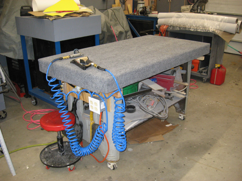
While the welding table is great, a steel surface isn’t ideal for upholstery. Some scrap plywood and a chunk of outdoor carpet dropped on top of the welding table converted it to a very sturdy work table. To make the table more productive I added a triple air outlet (to simplify the use of multiple air tools) as well as an electrical outlet.
Welding Table with Upholstery Top
Trim panels make extensive use of staples. A special type of staple – ones only 1/4″ long which don’t penetrate completely through the thin cardboard or hardboard used in these panels. Since you will be using literally thousands of these staples an air stapler is definitely the way to go. After a bit of research I ordered a Meite pneumatic stapler and a box of 10,000 staples.
The next item needed was fabric to build the test parts – specifically some fabric backed vinyl material. She Who Must Be Obeyed took me to JoAnn Fabrics where we found some vinyl on sale at 1/2 off and bought 6 yards. This was the first time I had been in JoAnn Fabrics as a willing participant. One thing to know is that they have a central station where they cut fabric to length and give you a slip of paper with the information you need to check out and pay. While standing in line at the register the cashier called out to me “excuse me sir – do you have the slip for that fabric?” I was able to answer “yes; I’m here with someone who knows what she is doing”. Apparently most guys don’t know how the store works…
We also picked up a couple of yards of 1/4″ thick fabric backed foam which is used on trim panels to give them a more luxurious feel.
I had enough scraps of 1/8″ hardboard left over from other projects to make the test panels and the first trim panels I wanted to do. Add in a can of spray contact adhesive and I was ready to get started! These first test pieces were just that – test pieces to be discarded after creation.
Getting started of course means reading the books on automotive upholstery I had previously purchased and spending many hours studying You Tube videos. I finally screwed my courage up to the sticking point, grabbed a cup of coffee, and started making a mess.
The process for making trim panels is basically cutting the backing to size, stretching the foam and vinyl over it, and stapling it on the back. With no bubbles, bulges, puckers, or wrinkles. Most trim panels have curved edges, making this a bit tricky.
Upholstery Test Pieces
“Mistakes were made”. The first test pieces had significant room for improvement. No surprise; that was why I was starting out with throw-away pieces. As She Who Must Be Obeyed has observed several times “it isn’t as easy as they make it look on You Tube.” I’m aware, I’m aware…
Go back to You Tube, study details that I missed the first time around, and head back to the workshop.
The next test pieces were better. Still not perfect, but considerably better. Hmmm, almost like this is a learning process…
Yup, this is the 100th post! When I started this blog in 2017 I really thought it would die of neglect after a year or so. While I was sure I could remember everything, She Who Must Be Obeyed pointed out that this wouldn’t actually happen in the real world and suggested I write things down. And maybe share it with other people. As usual She Who Must Be Obeyed was right.
The original thought was a notebook. But I type better than I write – with my handwriting I should have been a doctor. Understanding my scratches is more an exercise in deciphering than reading. And I was taking thousands of pictures of the Imperial with the goal of having a reasonable chance of putting it back together.
I had been writing a professional blog for a number of years – Techponder. Which has been woefully neglected since I retired. If you are having trouble sleeping feel free to take a look at it.
In any case, I had the knowledge, resources, and “talent” to start documenting these strange activities here in Imperial Journey.
Turns out that this blog was a good idea. There have been a number of times when I felt I wasn’t making any progress and looked though the blog. Whining about things like undercoating is surprisingly cathartic. The simple act of writing forces you to think. Believe it or not, there is actually thought behind these posts!
The workshop, the Imperial, and the other projects were an incredible help in maintaining what I use for sanity through the recent pandemic. Having something to do every day, having problems to solve, and having new things to learn was vital. It is amazing what obscure things Amazon, RockAuto.com, and a number of other vendors can deliver directly to your doorstep with no human interaction.
While much remains to be done, quite a lot has been been accomplished! Some of the posts, like the series on electrical wiring, have even been useful to other people.
So, to anyone reading this, congratulations on your bravery, I will not comment on your lack of taste, and I will continue writing until the mobs with pitchforks convince me to stop!
The original plan was to restore the Imperial in three stages: mechanical, paint and body, and interior. The original plan was also to accomplish each stage in a year, with three years for the total restoration. I’m now nine years into the project…
The first two stages are largely done. Some work remains, like HVAC and a new sound system, but the drive train, paint, and chrome are done and the car is on the road. It is now time to move to the third stage of the restoration: The interior.
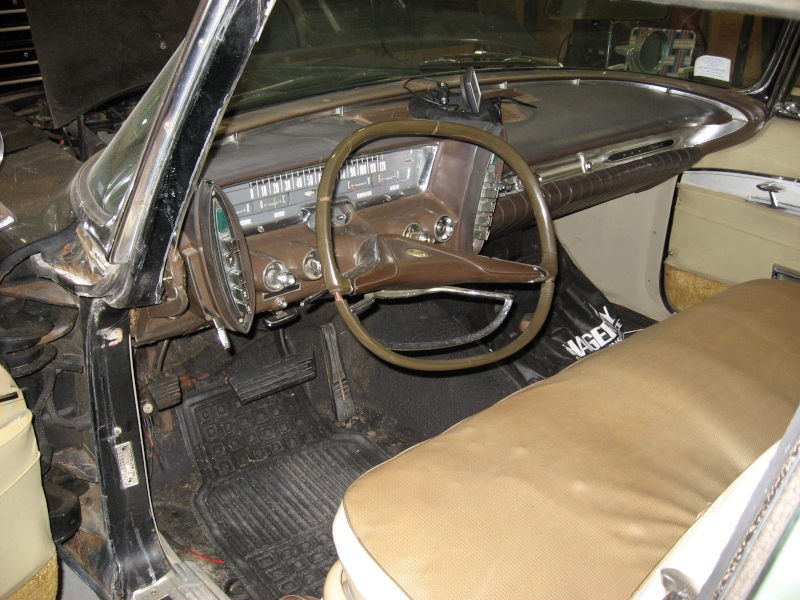
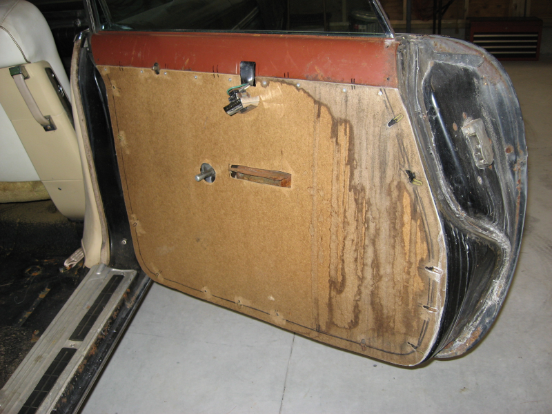
When the Imperial arrived, the interior was the worst part. Start with bare floorboards with no trace of carpet to be found. The front door trim panels were in decent shape, but were tired. Someone had started to replace the rear door trim panels, and had cut and fitted hardboard panels to replace the factory cardboard. There was no covering on these panels – they were just bare hardboard. They weren’t even on the doors – they were in the trunk. Some smaller trim panels were missing completely and need to be made from scratch.
Original Interior
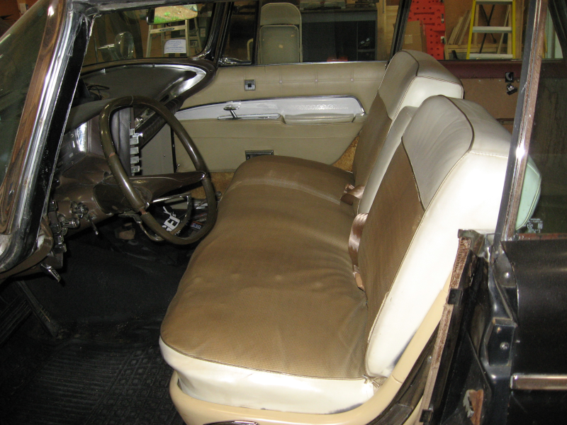
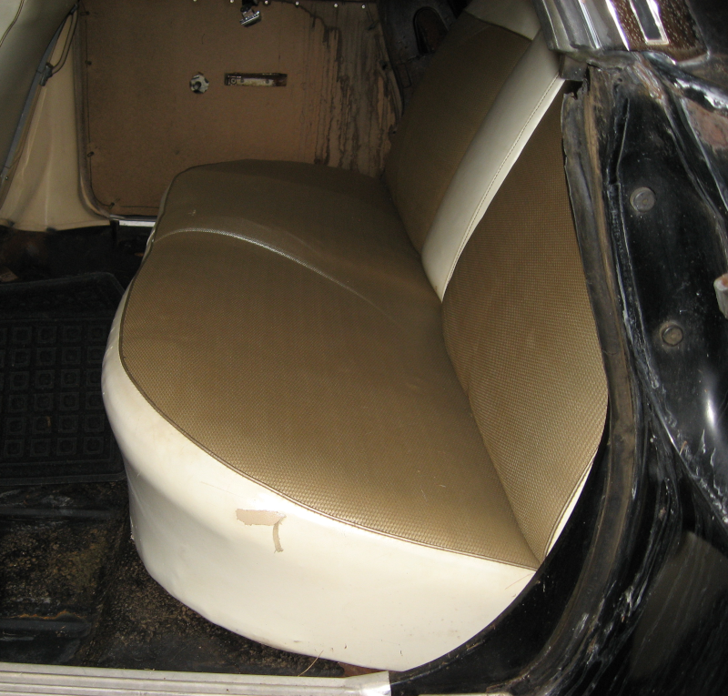
The seats had been re-upholstered at some point many years ago. Unfortunately they used a cheap vinyl that didn’t match the rest of the car. This vinyl is old, cracking, starting to tear, and dirty. Actually, it was filthy when I got the car – one of my first projects was a good cleaning of the interior!
Original Front Seat
The seats also have some structural problems: the drivers seat is very soft with little support. I don’t know if this is a problem with the foam, weak springs in this area, broken spring supports, or something else entirely. While fine for short drives, this is not comfortable for longer drives. The rear seat has some springs actually poking through the cover – certainly not comfortable! When I took the rear seat out there were chunks of old degraded foam all over the floor.
Rear door card – bare hardboardRear Seat
The one bit of good news is that the headliner has been replaced. The new headliner is high quality, extremely well fitted, and looks great. Since it is difficult to do a good job installing these old style headliners I have been very careful not to disturb it! This has had some downsides – I wasn’t able to install any sound deadening material or insulation in the roof when I was doing the rest of the car, and I wasn’t able to install mounting points for a shoulder harness so only seatbelts have been installed.
Special skills and equipment are needed to do upholstery and interior work, so I tracked down a good interior shop and got a quote.
$15,000.00. Plus materials – leather would probably add another $3,000-$5,000. And over a year before they could start on it.
Not happening.
Anyone who has been following this little saga will have realized that I have very little sense of self preservation. After a bit of research my thoughts ended up at “well, I learned how to do bodywork and welding, so I should be able to learn upholstery and sewing.”
If I plan up front to start with practice pieces to learn on, take my time, and stay willing to start over and re-do things until I get it right I should be able to get acceptable results. Right?
She Who Must Be Obeyed has many years of experience sewing and is laughing at me. She points out “you know, it isn’t as easy as it looks on YouTube.” Yeah, I’m aware of that… She also has the sense to stay well away from this project.
I also understand that skill is something you end up with, not something you start with. And this is a chance to get new tools!
So, join me as I get frustrated and annoyed, pound my head against a brick wall, and hopefully able to eventually give the Imperial an interior to be proud of!
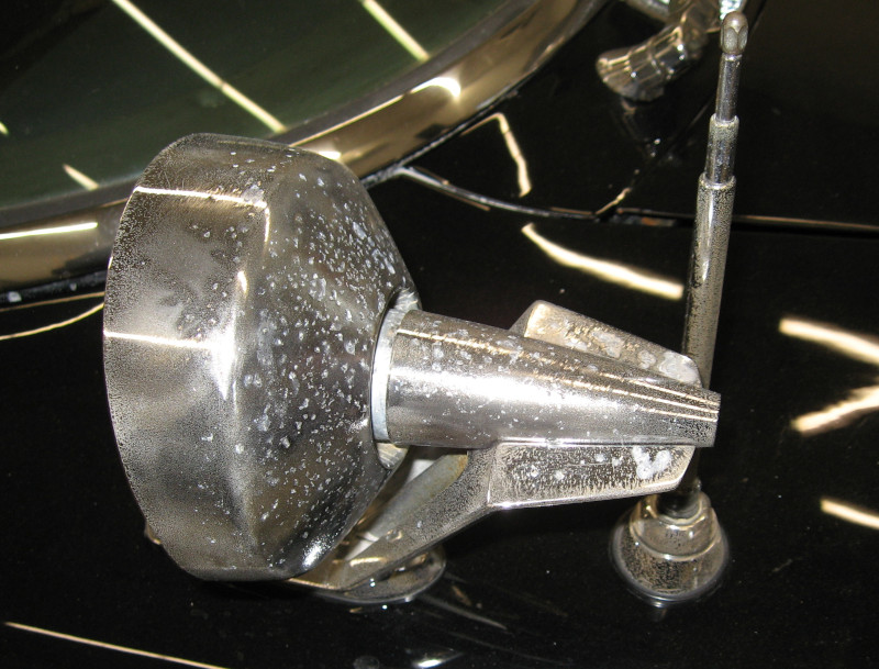
The outside mirrors were some of the worst chrome trim on the car. The pot metal was heavily corroded and pitted. After painting the car and getting the rest of the chrome re-plated these were easily the worst part of the car, bringing down overall appearance.
Old mirrors – definitely in rough shape!
Why weren’t these done with the rest of the trim? Cost. Each mirror would cost $650 to restore, because of the extensive work they needed to correct the pitting.
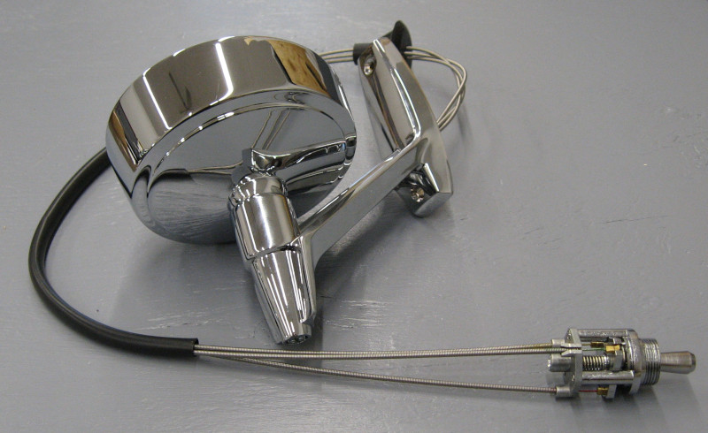
Good news! I managed to track down new reproduction mirrors for only $175 each. While Imperial specific parts are hard to find, these mirrors were listed for 58-66 Imperial, 58-64 Chrysler, and 58-62 Dodge Plymouth Desoto. This is a large enough market to support making reproduction parts.
I ordered two of the mirrors and was pleasantly surprised by the high quality when they showed up.
Installing them was a bit of a job. Mounting most rear view mirrors is a case of two screws and you are done. Of course it isn’t that easy on an Imperial! The Imperial mirrors are remotely adjustable, so the control cables have to be routed from the front fender to inside the cabin and installed in the dashboard.
New mirror with remote control
As expected, the mirrors are mounted on top of a sealed compartment with no access other than a couple of 1″ holes, making it a bit of a nightmare to route the cables and adjuster… With creative use of a number of tools, patience, and an application of appropriate invective the cables were finally in place.
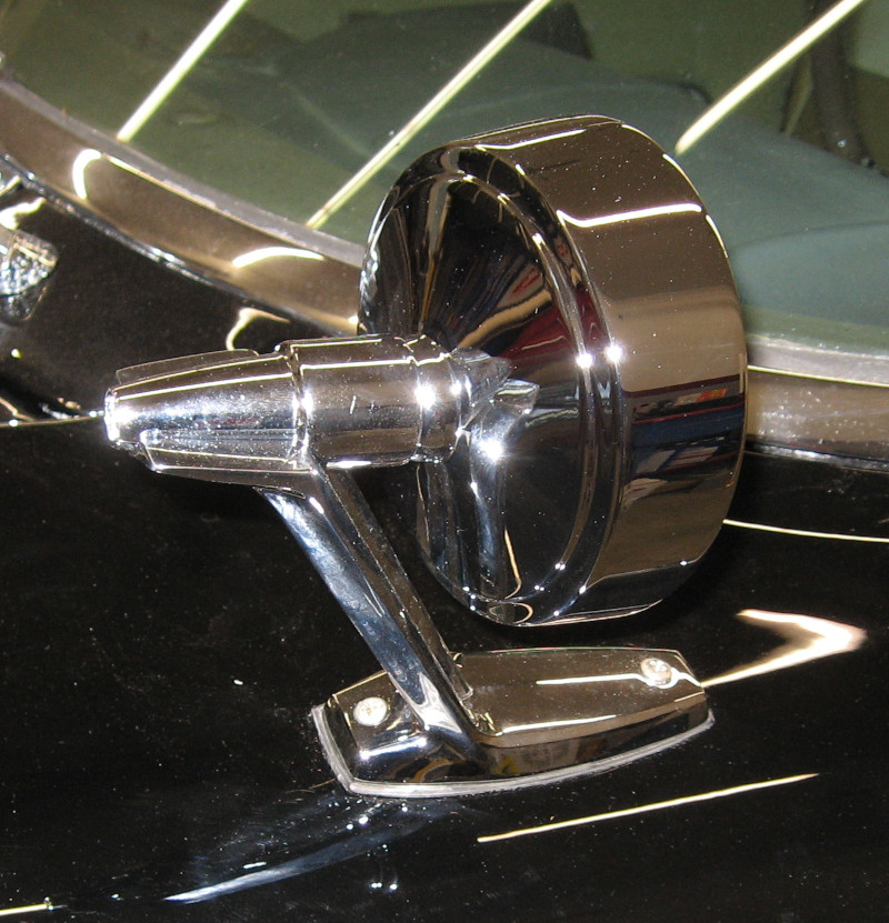
With the cables run the actual installation of the mirrors was, in fact, two screws and 30 seconds of time.
New Mirror installed
The new mirrors look great and work well. Another big step forward for the Imperial!
Another big time consumer this summer was travel. In July we did something we’ve been planning for years – headed up to Alaska.
I lived in Alaska for three years, but that was fifty years ago. My biggest question was whether or not I would recognize and remember anything! She Who Must Be Obeyed had never been to Alaska, so it was about time.
We ended up choosing a two week fly/cruise/train expedition: Fly into Vancouver, Canada, cruise up the Inside Passage to Seward, take a train to Anchorage, take another train from Anchorage to Denali National Park, three days in Denali, a bus to Fairbanks, and then fly home.
This was our first cruise and we had concerns about it. No need for concern, we loved it! The Inside Passage is completely smooth. The only way you could tell the ship was moving was to look out the window. Our balcony cabin was comfortable and offered great views. Food was great and there were things to do. We had three shore excursions and got to do a variety of things like whale watching.
Humpback whales feeding Juneau AlaskaCruise ship docked in Skagway, AlaskaWhite Pass Railroad. Fortunately this bridge isn’t in use…
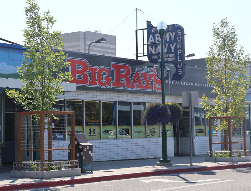
I didn’t recognize Anchorage at all, even after living there for three years. This was a combination of changes to the city and fuzzy memory. I did recognize one thing: the 1950’s style sign for 4 Ave. Army Navy Surplus store – one of my favorite places 50 years ago. Great disappointment when I walked up and discovered that it was now Big Ray’s Alaska Outfitters…
Sadly no longer actually 4th Ave. Army Navy Surplus
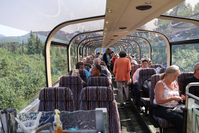
From Anchorage we took the domeliner train to Denali National Park. Great views and a good ride.
Domeliner cars on Alaska Railroad
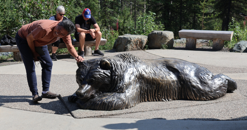
At Denali we took a bus ride 42 miles into the park. Unfortunately we didn’t see Mt. Denali (formerly Mt. McKinley), but we did see a mother bear and three cubs. At a distance…
Alaska Brown Bear in the wildBronze bear at the visitor center
Leaving Denali we took a bus into Fairbanks, spent the night there, and then flew home.
Gift shop in downtown Fairbanks, Alaska
All in all a great trip! It did take a lot of time to plan, prepare for, and recover from. All of which kept me away from working on the Imperial.
Then in October we drove to Oklahoma to see family. As we usually do, we spent some time driving around back roads we hadn’t been on before. Driving through the small town of Chickisha we did a sudden double take – there in the center of town was a 42′ tall leg lamp, straight out of A Christmas Story! Not what you expect to see in rural Oklahoma!
Leg Lamp in Chickisha, OK. Google for details if you don’t believe me!
While I didn’t get any work done on the Imperial I did manage to get out to several local car shows. In the past I would get comments “what a neat car!”. This year I got comments “what a beautiful car!”. The hard work is beginning to pay off!
It has been way too long since the last update. I have a weak excuse for this – I haven’t actually done anything to the Imperial… The summer has been consumed with other projects:
The first major project was finishing off the three season room we started last fall. We ran out of time last fall to install the Trex decking, so as soon as we had decent weather it was time to strip off the 35 year old pressure treated deck boards and replace them with Trex. Specifically, a 12′ x 21′ deck, a 6′ x 8′ landing, and two stairs. Fairly straightforward, but time consuming.
Once the decking had been replaced new railings were needed. I made the mistake of letting She Who Must Be Obeyed find my stash of Fine Homebuilding magazine. She liked cable railing. OK, check the companies that make them, punch some information into their online estimator, and choke on the price.
While contemplating the situation it hit me – I have a welder and I’m not afraid to use it! Time to research how cable railings are made, design a complete railing system, and retreat into my fabrication shop.
Following my usual approach of overkill, the railing was designed with steel tubing – 11 gauge 2″ x 4″ top rail, 11 gauge 2″ x 2″ uprights, 11 gauge 1″ x 2″ bottom rail, and laser cut 3/16″ thick 6″ x 6″ mounting plates. This is probably three times as heavy as a commercial railing system. Since steel tubing comes in 24′ lengths I was able to build the entire 21′ long main rail as a single piece – the commercial railing systems would require three pieces for this. Time to cut, weld, and assemble the main railing, including turning some custom fittings on the lathe to allow the railings to be bolted together with hidden bolts. This was followed by the traditional three coats of paint.
The 3/16″ stainless steel cable for the horizontal rails was actually fairly easy to install once I got the proper fittings and a hydraulic crimper.
The main railing was ready to install. All 200 pounds of it. Six feet up in the air. And it had to be held in exact position with precision alignment while it was bolted to the deck frame. By two people who are past the point of heavy lifting. Yeah. No.
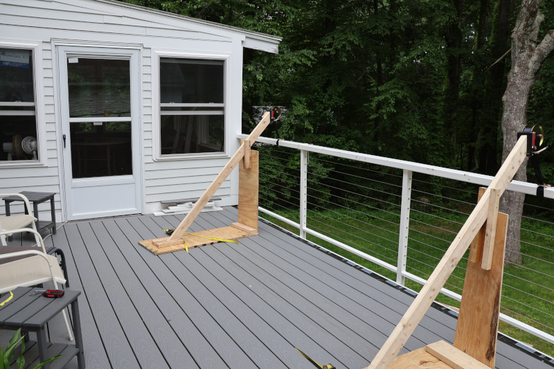
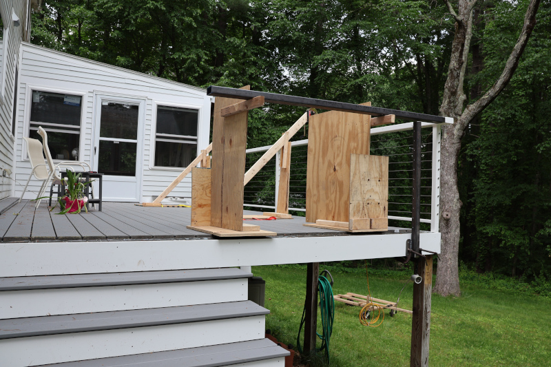
While brainstorming alternatives an inspiration suddenly hit with an audible thud: For lifting, get a couple of cheap boat winches from Harbor Freight and make derricks out of scrap lumber. For precise positioning make a couple of supports out of scrap lumber at exactly the height of the railing. And to move the railing from the workshop to the deck use the wheeled cart normally used to store kayaks.
Derricks lifting main railing into place
With the main railing in place the second section was mocked up, fitted together, and tack welded.
Fitting second railing section.
Once this second section of railing was completed, painted, and installed that last step was to fabricate and install left and right stair railings:
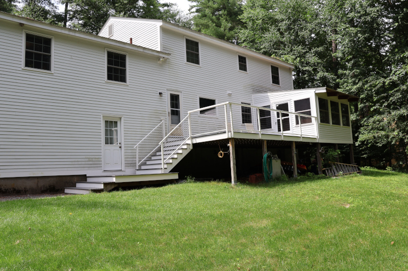
Finished deck and railing
The railings turned out great! Actually, too good… After seeing the finished railings She Who Must Be Obeyed decided that we needed the same sort of railings for the front entry and the stairs up from the driveway. I couldn’t argue with this, these additional railings were needed for safety. So, drag out the welder and keep going. I had actually planned for this and ordered enough steel tubing initially to cover this. A few days of fabrication, three coats of paint, a trip to Harbor Freight for an SDS concrete drill to mount railings on the sidewalk, and the front of the house was ready for winter ice.
With everything finished it was time to call the mechanical inspector for a final inspection and then move on to electrical. About that… When I called I was informed that electrical had to be completed before mechanical could be signed off. Sigh. Why couldn’t they have told me this last fall?
OK, put together an electrical materials list for the three season room, get the parts, and start wiring. Of course it wasn’t quite that simple. We have an emergency generator wired into the main electrical panel – we tend to have trees come down on power lines in the middle of winter, and have had power outages lasting up to two weeks. Part of the electrical plan was to move the generator inlet from inside the three season room (previously known as a screened in porch) into the garage. This was an additional several days work.
Of course it wasn’t quite that simple. Between the time we started this project and now we were forced to get rid of our 10 year old, 300,000 mile CMax. We replaced it with a Ford Mach-E, which is an electric vehicle. This meant adding a 240 volt EV Charging Station in the garage. “Normal” people do this with a 30 amp circuit and a dryer outlet. I looked at the specs for the Ford Charging Station we selected and saw that it could charge at up to 48 amps. Since continuous electrical loads require that a circuit be de-rated, a 60 amp circuit was required. No problem! All it requires is 6 gauge wire and a 60 amp tandem breaker. Except that the main panel is completely full… Nothing that a few hours studying the existing circuits to allow combining some circuits as well as shuffling around some existing breakers so that the new tandem breaker can be installed won’t handle.
The wiring for the generator inlet and the EV Charging Station were combined into a single project so that a single new conduit could be run from the main electrical panel to the garage. A total of three 6 gauge wires and four 10 gauge wires were required. An electrical fill calculation showed that 1″ electrical conduit was needed, so 1-1/4″ electrical conduit was used. The new SDS drill was used to drill a 2″ hole for the conduit through the one foot thick basement wall, making this job easier than originally planned. (The fittings for 1-14″ conduit are 2″ in diameter.)
With the generator inlet out of the three season room the new electrical wiring was installed. A rough electrical inspection was scheduled, and the inspector found a few minor things to quibble with. The final electrical inspection was scheduled and passed.
At some point during this time we picked out new flooring for the three season room. We chose a solid vinyl plank flooring with is about 1/4″ thick and very heavy. It should also be very durable. And very waterproof. This of course took me several days to install.
Now, finally, I could call for the final, final, final inspection. Which passed. And there was much rejoicing! This three month project was completed in under a year, which I’m going to claim as a win.
About how heavy the railing is: the inspector tried to wiggle it and noted that it was absolutely solid, completely rigid, and didn’t move at all. He laughed and said that he wasn’t even going to bother checking for the 185 pound lateral load railings are supposed to handle.
With the paint finally finished the next step was to reinstall all of the trim on the car – all 873 pieces of it. There are three types of trim pieces on this car – steel (mainly the bumpers), cast pot metal, and stainless steel. Each requires different treatment.
The bumpers were straightforward – just bolt them into place with 1/2″ bolts. The only real challenged was wrestling these three ton parts into place long enough to get the bolts started. By myself… OK, maybe they are only 50-60 pounds, but that is still a lot heavier than it used to be!
The cast metal parts use threaded studs that screw into threaded bosses on the part. In the past I’ve used the double nut approach – screw two nuts onto the stud, tighten them against each other, and use this to screw or unscrew the stud into place. This works well, but it is time consuming and tedious.
Looking through the Bolt Depot website I happened to notice set screws. Just a minute – these are just like threaded studs, except that them come in various lengths and have a hex drive! They are also available in stainless steel at a reasonable price. OK, I need a couple of bags of these! They worked great; much easier to screw into the parts than threaded studs. The parts installed just like with the original studs. They should, since the only difference between the threaded studs and the set screws is the hex drive.
All in all the only real challenge with the cast metal parts was the cost of having them re-chromed.
The stainless steel side molding trim had been giving me heartburn for the last couple of years. These parts are formed sheet metal and are held in place with plastic clips. The 60 year old plastic clips break when you breathe on them – I broke practically all of them removing the trim from the car. And, of course, they aren’t available. Modern cars either don’t have trim like this, glue the trim in place, or use different styles of retainer clips.
Around two in the morning inspiration struck. A couple of weeks later I actually remembered it during the day: what about making a square tab out of sheet metal to fit in the mounting grooves in the trim pieces? Time to head out to the workshop and make some test pieces! Measurements suggested that 3/4″ would work. A piece of scrap sheet metal was cut to size and proved to fit perfectly.
This left the issue of attaching it to the car. Instead of a snap-fit plastic part, what about welding a bolt to the tab and securing it with a nut inside the car? Nope, wouldn’t work. The nut is too thick. Just a minute – what about a piece of threaded stud? Weld a stud to the tab, slip the tab into the trim piece, position it on the car, and screw on a nut from the inside. Well, would you look at that – works perfectly!
Counting mounting holes in the car told me that I needed to make about 50 of these mounting tabs, each exactly 3/4″ wide. With rounded corners. The threaded studs I had were too long, so I had to cut them in half and weld them exactly in the right place. Not looking forward to this!
Having a solution was good. Implementing the solution would be annoying. Just a minute – this is the kind of thing SendCutSend does! Hop onto the CAD system and design a 3/4″ tab. With rounded corners. And a hole in the center to locate the threaded stud. Hmmm, for this part the pricing is the same for mild steel and stainless steel… OK, stainless it is!
And then another thought struck – didn’t set screws come in various lengths? Yes, yes they did! Set screws were available in the 1/2″ length I needed. And stainless steel isn’t much more expensive than mild steel. OK, these mounting tabs are never going to rust.
I needed some way to hold the tab and set screw in place while welding them. Something that would hold the set screw perpendicular to the tab. Ideally something that would position the end of the set screw even with the back of the tab.
What about taking one of the chunks of 5/8″ steel plate left over from an earlier project and drilling a hole in it? Drill the hole just deep enough that the set screw will stick out just enough to locate a tab when you drop it over the screw. This locates and squares everything and the steel plate won’t be affected by welding heat.
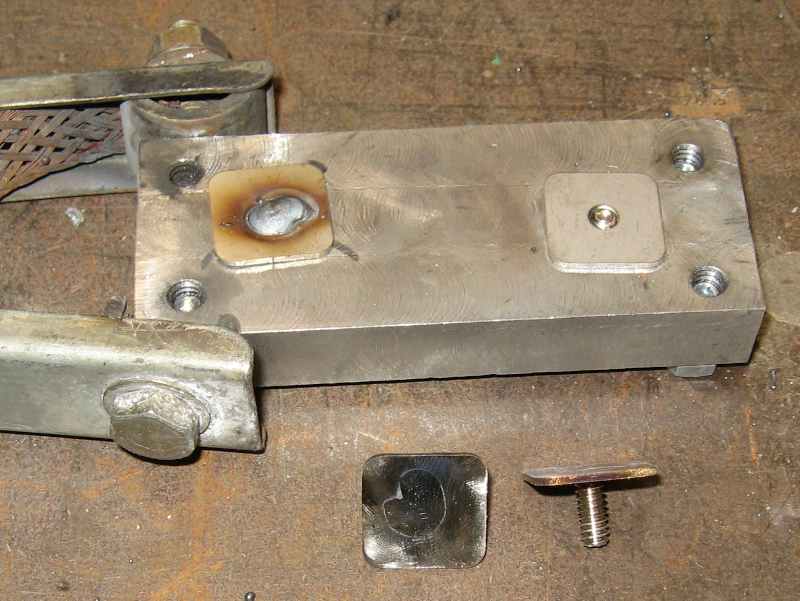
So that is exactly what I did – mill one surface of the plate flat, drill a hole the proper depth, and start making trim retainer tabs!
Jig for making trim retainer tabs
Top right: tab ready to weld to set screw. Top Left: Tab welded to set screw. Bottom Left: weld on tab ground flat. Bottom Right: Finished trim retainer tab. Note the ground clamp on the jig block – welding works much better when you remember to do this!
Being paranoid, I took the first half dozen retainer tabs and used them to test mount several different pieces of trim. They all worked so I went ahead and made the entire batch. There were several places where the trim originally used threaded studs and the 1/2″ studs I was using were too short. For these I made a set of retainer tabs with 1″ threaded studs.
Everything went together reasonably well. There were a few places where I couldn’t reach to get the nuts on, but the trim pieces were well secured with the ones I could reach.
The trim around the rear window was also stainless steel. It was wider than the side molding trim, and already used metal tabs and threaded studs. These tabs were wider and the studs were longer – 1-1/4″ vs. 1/2″ since they needed to go through the heavy rubber molding that secures the rear window. These studs were also smaller – 8-32 vs. the 10-24 studs used in the side molding. In addition, the studs were offset from the center of the tab.
Unfortunately 8-32 set screws don’t come in 1-1/4″ length. But bolts do… Fine, order a bag of 1-1/4″ bolts and cut the heads off!
Most of the old tabs had rusted out. Fortunately there were enough good ones that I could take measurements. Hop back onto the CAD system, design these tabs, and include them in the same SendCutSend order as the side molding tabs.
The welding fixture worked really well for the side molding tabs, so it was modified for the rear window tabs. In addition to needing a smaller hole it needed some way to control the length of stud sticking up from the top of the block. Four screws to a great job of providing this adjustment.
Trim Tab Jig with height adjustment bolts
A few minutes of adjustment and the new trim tabs were welded up and ready to go.
While the stainless steel trim itself was in good shape, it had 60 years of exposure to the elements. Metal polish on a felt pad in a die grinder brought it back to a factory fresh luster.
All of the trim is back on the car and looking good. I think I’m ready for the first Cruise Night of the year!
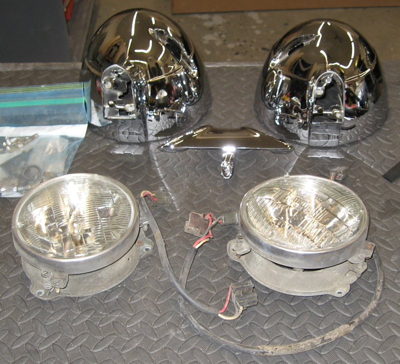
With the beautifully chromed headlight buckets ready to install it is time to complete the job of upgrading headlight wiring. You may recall from a previous post that I left the original factory wiring in the headlights themselves, waiting for the chrome plating to be done.
Headlight components ready for assembly
This picture shows the freshly chromed headlight buckets, the crossmember that connects the two buckets on each side, the mounting hardware for the headlights that goes inside the buckets, and the original factory wiring. The wiring goes up the base of the inner bucket and then through the crossmember to the outer bucket.
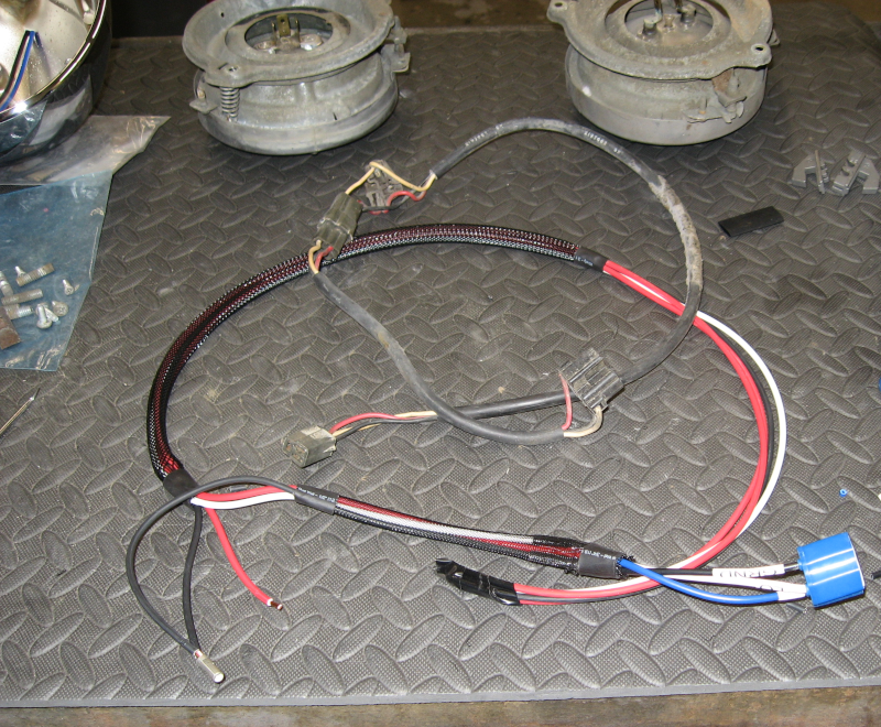
Old wiring harness and new harness
The original harness had two inline connectors. It also had a single 16ga wire for the low beam, a single 16ga wire for both hi beams, and a single 16ga ground wire. Between long runs of thin wire, multiple connectors, and 60 years of corrosion there was noticeable voltage drop to the headlights.
The new harness has a single connector, which is now a waterproof WeatherPack connector. It has a dedicated 12ga wire for the lo beam, two 12ga wires for the two hi beam headlights, and a 12ga ground wire which directly connects to the battery. As a reminder, power for the headlights now comes directly from the battery going through relays. Wire length has been reduced from 8′-12′ for the factory wiring to about 3′ with the new wiring, further reducing voltage drop.
All connections are sealed with marine heatshrink tubing with glue. Wire harness braid is used for both appearance and protection from chafing. Also note that the wires are labeled – this continues to save me from mistakes!
The actual socket that the headlight bulb plugs into is now a high temperature ceramic socket. The factory headlights were 35 watt while new headlights are 55, 65, or even 100 watts. With new bulbs the headlight buckets might trap enough heat to melt normal plastic sockets. While I probably won’t run 100 watt bulbs I do plan to upgrade to 65 watt bulbs.
Since I knew exactly how to build the new headlight harness I only had to rework it four times. And the second harness went even faster!
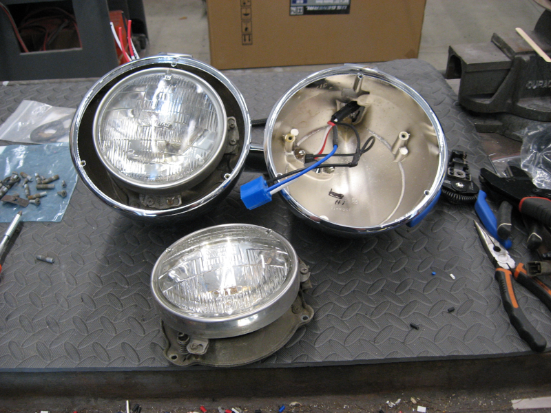
Installing headlights into headlight buckets
With the headlight buckets attached to each other through the crossmember the headlight mounting hardware is installed in each bucket. The headlight bulbs are plugged into the new ceramic sockets, positioned in the mounting hardware, and secured with the retainer ring.
Chrome trim rings (not shown) are installed on the front of each headlight bucket and the headlights are finally ready to mount on the car! This was a simple job, so this 15 minute task only took me two hours.
The only thing left to do was illuminate the workshop with now high powered headlights! Which I proceeded to do with lo beam and no high beam. Krud.
I quickly determined that I had swapped the lo beam and ground wires on the connector. Fortunately I was able to remove these two pins (thanks to having the foresight to buy a WeatherPack de-pinning tool…) and move them to the correct locations. NOW I had bright lo beams and hi beams! The second pair of headlights worked the first time.
For now I’m still using the original sealed beam halogen headlight bulbs. These will be upgraded to modern H1/H4 bulbs when finances allow. Or when I start driving at night, whichever comes first.
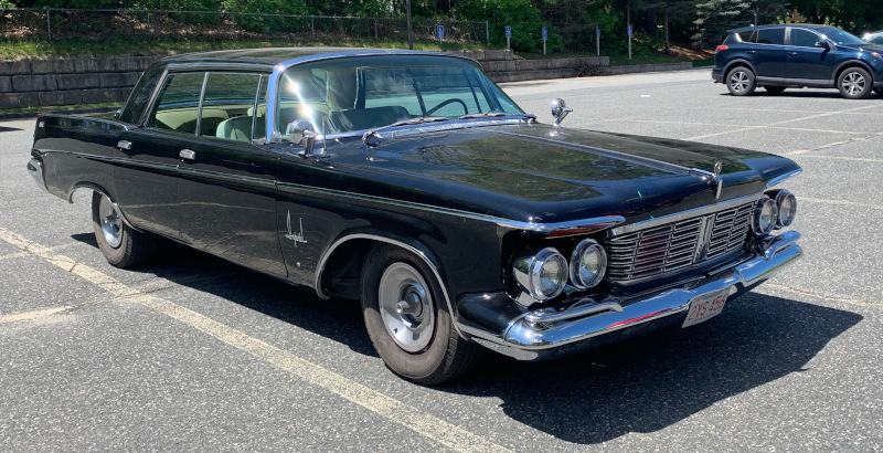
Introducing the Imperial Deathstar, a black 1963 Chrysler Imperial. This is one of the largest production sedans ever built, and arguably the best luxury car of its day.
Join me what will probably be a never-ending saga of grease, aching muscles, and an empty wallet as I work to restore this over 50 year old survivor to a reliable cruiser.