Just back from the last car show of the year at Kimball Farms. I wasn’t originally planning to attend, as I had gone to the one last week, but the weather was absolutely beautiful. OK, once more into the breach!
Except the Imperial wouldn’t start – low battery. Hmm, a problem with the battery or do I still have an electrical problem? Slap the charger on the battery and in a half hour it recovered enough to start. Well, I have a boost pack in the car, so I should be able to make it back home.
Throwing caution to the winds let’s get this car on the road! Hmmm, while driving along I see that the courtesy lights are going on and off… Wasn’t this problem solved? And after parking at the show the courtesy lights stayed on. Not good. Concerned about running the battery down I headed home earlier than planned, disconnected the battery, and slapped the charger on it.
Had a bit of excitement on the drive over: someone blew through a stop sign on a cross road right in front of me. The only possible response was to stomp on the brakes as hard as possible. The new brakes showed their worth, instantly locking all four wheels and stopping in a straight line. It is a good thing I missed the other car – it probably would have totaled his car and scratched the new chrome on my front bumper!
Now back to our planned posting: This was a good summer. The decision not to do any major projects over the summer and to instead actually drive the car (although not enough…) was a good one. The Imperial runs well, draws attention, starts conversations, and is fun to putter around in. In retrospect the only mistake was that I should have driven it even more!
And now Winter Is Coming. Looks like I have a good collection of projects to plan. Why don’t I mention them here so that we can all have a good laugh next spring?
Interior
First on the list is the front door cards. These still have the factory vinyl on them, so I need to take them out and recover them like I did with the rear door cards. I also need to apply the felt window filler strip to all four windows.
The existing outside door handles are chrome (like everything else on this car!) and are a bit rough. I found some new reproduction front door handles. It will be a bit of a nightmare to replace these without removing the entire window regulator mechanism, but we will see how it goes.
The good news is that all four of the power windows are working well – track adjustment and electrical upgrades to the windows have them going up and down with authority. The master switch – the one in the drivers door that controls all power windows – wasn’t working for the front passenger window. I got a new (used) master switch and it now works for all four windows. Except the front passenger window goes down when you press up and up when you press down. Looks like I reversed the wires for this particular switch and had no way to check them. Should be an easy job when the door card is off.
Since I’m never smart enough to leave things along I think I want to do a custom trunk – add panels like the door cards to completely finish the inside of the trunk. I’ve seen trunks done this way and they look great. I think I’ve got enough fabric left from the interior to do this, so the only real cost is time. Right? Well, there is the tiny detail of learning how to do custom carpet for the trunk floor…
I need to install speakers in the rear deck and add a finished cover. Currently it has a piece of indoor/outdoor carpet laying there. Doesn’t look bad, but could be finished better.
I’ve been thinking off and on about how to add a center console on the floor of the front seats. The car really needs cupholders and this is a good way to get them. And maybe put some front speakers in the console rather than cutting up the doors or front trim.
I also need to decide what to do with the radio. The choices are 1) Do nothing. 2) Upgrade the factory radio. 3) Add a new radio. Note that the factory radio is Imperial specific and you can’t find other radios with the needed bezel.
So far the approach has been to do nothing. In practice this means I haven’t even turned the radio on. There are companies that will upgrade the factory radio with new electronic guts. This gives you modern sound and features like bluetooth phone support and streaming playback with a complete stock factory appearance. Unfortunately the radio now in the car has been hacked up so badly that I would have to get a donor radio to upgrade.
Which leads us to a new radio. The question is where to mount it. As mentioned, the factory radio has a custom bezel that fits the curved dash. I’ve been thinking about ways to make a new bezel – this could be an excuse for getting a 3D printer. Other choices include putting the radio in the glove compartment or putting it in a center console on the floor. The glove compartment is easy to do and seems to be the most common approach, but is difficult for the driver to use. If I can come up with something that fits the center console is looking attractive.
Detailing
I’m embarrassed to admit it, but I still haven’t detailed the car. All of the paint correction, including sanding, polishing, and waxing, left flecks of polish and wax all over the place. I need to spend the time with a toothbrush and towel to clean all traces of white from this black car!
After that I need to wash the car more regularly. It tends to pick up dust from various projects in the shop and from sitting outdoors.
The tires need to be cleaned and detailed; a judge dinged me for this at a show.
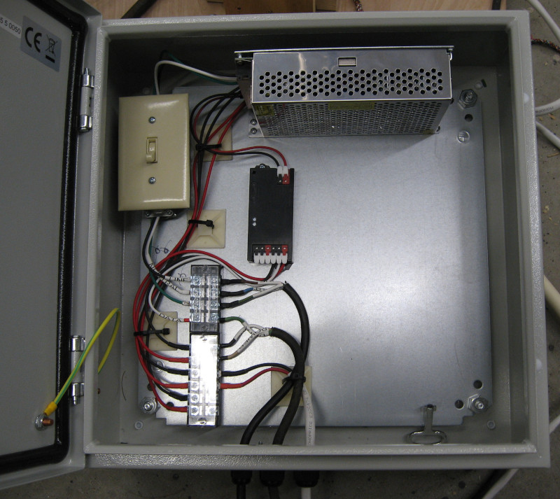
Electrical
Sigh. The courtesy light problem is back. It looks like it wasn’t the LED replacement bulbs after all. In the short term I need to locate the power feed for the courtesy lights and disconnect it. After that the only real solution is to build a complete custom electrical harness for the courtesy lights: All new wiring, new switches, and perhaps even new sockets (if I can find them). There is something subtle going on here and it is time for a complete rip and replace if I want to have courtesy lights.
It may also be time to add a master kill switch to disconnect the battery. An easy to access switch is better than disconnecting the battery cable each time. And this would also be a safety and security feature. Need to dig into this a bit more.
I need to clean up the wiring from the new LED lighting for the heater controls. The dimmer control was left hanging under the dash for testing – it needs a permanent home.
It would be nice to have a light in the trunk. I have the light – it was in a box in the trunk. Need to figure out how to install it.
Most of the high current electrical devices in the car have been put on relays. The last ones undone are the HVAC system – the three speed fan and the AC clutch. The original switches for the fan had burned out. The new switch is working, but adding relays would add a big chunk of protection. Challenges include figuring out wiring and finding a location for a relay box.
There are still six gallons of gas in the tank when the fuel gauge reads Empty. I should think about adding a MeterMatch while doing the rest of the electrical work.
Mechanical
The hood isn’t closing properly. I have a new hood hinge that needs to be painted and installed.
More cooling work is needed. Then engine only runs warm on hot days under load – like running down the Interstate at 70. Engine temperature is nominal during cooler weather – the temperature comes up to normal and then stays there. This indicates that the temperature gauge and thermostat are working correctly. I know that the thermostatic fan clutch isn’t working, so the next job is to replace it. I’m wondering if the water pump is working at full capacity; need to think about replacing that if the fan clutch doesn’t do the trick.
I really have to get after the transmission leak. This needs to be resolved before any significant trips. I know I need to replace the O-rings for the shift cables. This should have been done when the transmission was out of the car. I stripped one of the bolt holes on the transmission cover the last time I was working on it. I need to drop the transmission pan and helicoil that bolt.
Beyond this I don’t know what to do. May need to thoroughly clean and dry the transmission and see if I can determine exactly where the leak is.
There is still a bit of vibration when accelerating between 25-30mph. It is much less than it was – has gotten better as the new suspension settles in. The next step in try to fix this is to remove another leaf or two from the rear springs. Unfortunately the 4-bar linkage in the rear suspension makes this a bigger job than it should be.